n If the outdoor unit is installed on a roof, it and
the supporting structure must be earthed sepa-
rately (connection to a lightning rod or a con-
crete-footing earth electrode).
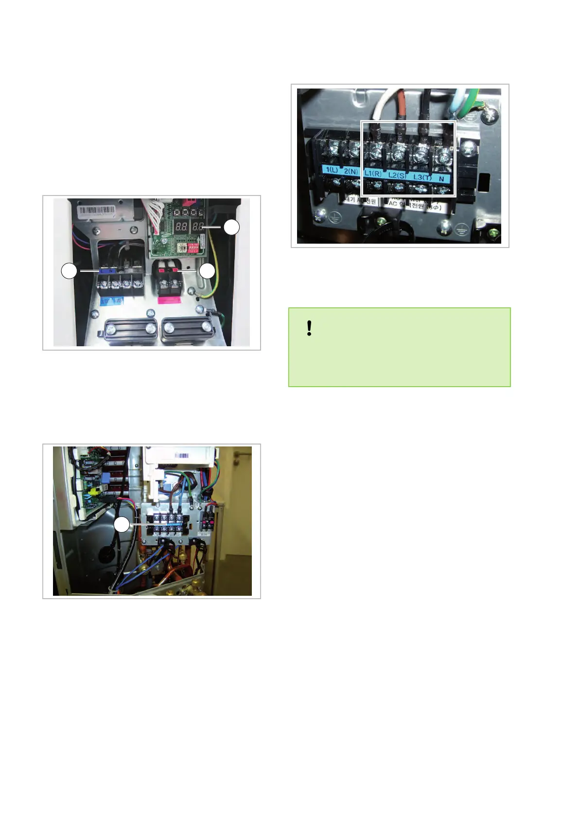
n In the series WKF/WKF-compact 180 it must
be ensured that only the terminals L1(R),
L2(S), L3(T) and N are connected (see
Fig. 10).
Fig. 8: Connection terminals - outdoor unit
WKF/WKF-compact 70
1: Display
2: Power supply 230V/1~ /50Hz
3: Control cable F1/F2
Fig. 9: Connection terminals - outdoor unit
WKF/WKF-compact 120
1: Power supply 230V/1~ /50Hz
Fig. 10: Connection terminals - outdoor unit
WKF/WKF-compact 180
NOTICE!
Make sure to connect the outdoor unit neutral
connector properly
, otherwise the varistors on
the line-filter circuit board will be destroyed.
Temperature sensors
n The number of sensors required can vary with
the type of system.
n Observe the pertinent notes for the sensor
position found in the hydraulic schematic.
n The standard model includes an external
sensor (S10), a submersible sensor (intended
for use as a custom hot-water sensor (S08)
and a sensor for a total inlet at the indoor unit.
n When connecting solar panels, the PT
-1000
sensor (S01) as a collector sensor and a
PT-1000 sensor (S02) as a lower storage tank
sensor must be used.
n All sensors are to be connected to the indoor-
unit switching-cabinet according to the ter-
minal-assignment diagram.
REMKO WKF series
14

 Loading...