SECTION 1
GETTING ACQUAINTED
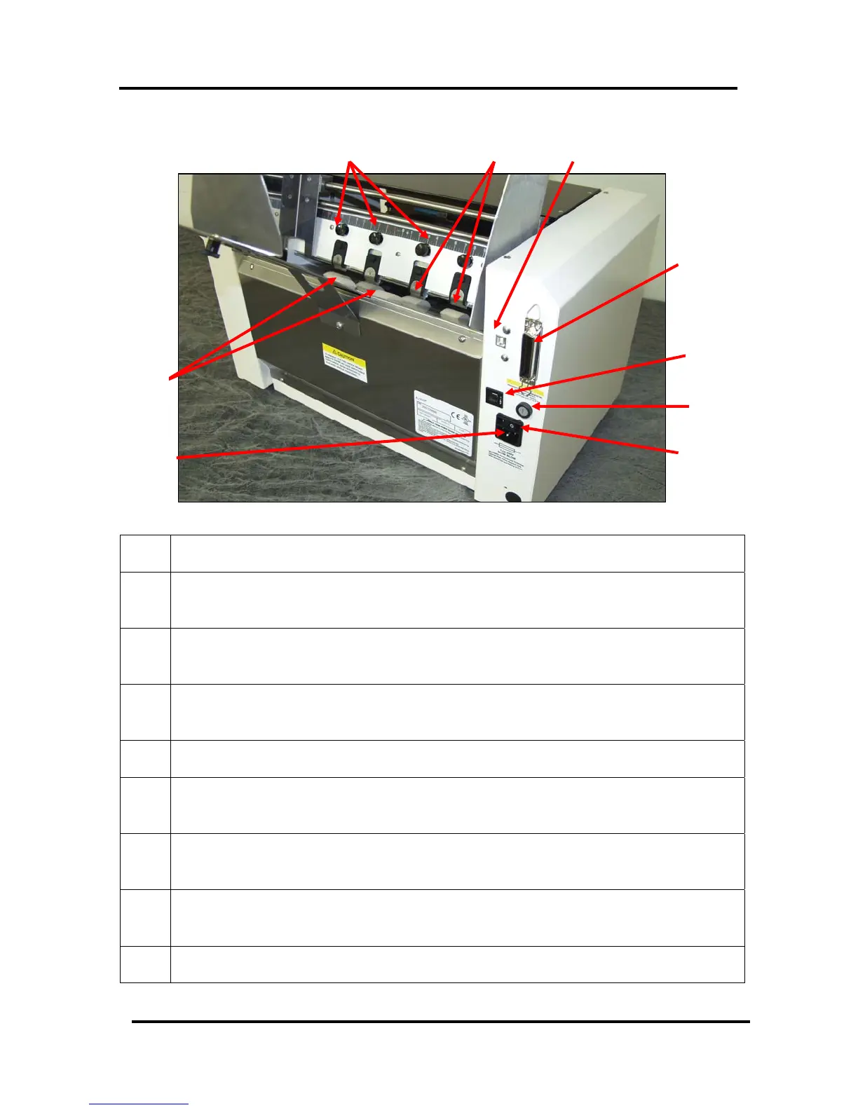
Rear View
10
11 12
13
9
14
15
16
8
Figure 7
8.
POWER RECEPTACLE – The power cord is plugged in here.
9.
FEED ROLLERS (six) – Delivers the bottom piece of media, from the stack,
through the separation area, and under the forwarding rollers.
10.
SEPARATOR LOCKING KNOBS (four) – Used to lock the separators in place
after they are adjusted.
11.
SHEET SEPARATORS (four) – Used to separate a single piece of media from
the stack.
12.
USB PORT – Connects the printer to the USB port on your computer.
13.
PARALLEL PORT – Connects the printer to the parallel printer port on your
computer.
14.
MOTOR CIRCUIT BREAKER – The circuit breaker protects the printer’s
motor from overload.
15.
MAIN POWER FUSE – This fuse protects all of the electronic circuits in the
printer.
16.
MAIN POWER SWITCH – This switch turns the printer ON and OFF.
Envelope Imager 1.5/1.5 Plus Operations (Rev.6/7/2007)
9