E2 Lite Outline
R20UT3240EJ0300 Rev.3.00 Page 17 of 36
May.15.20
E2 Lite
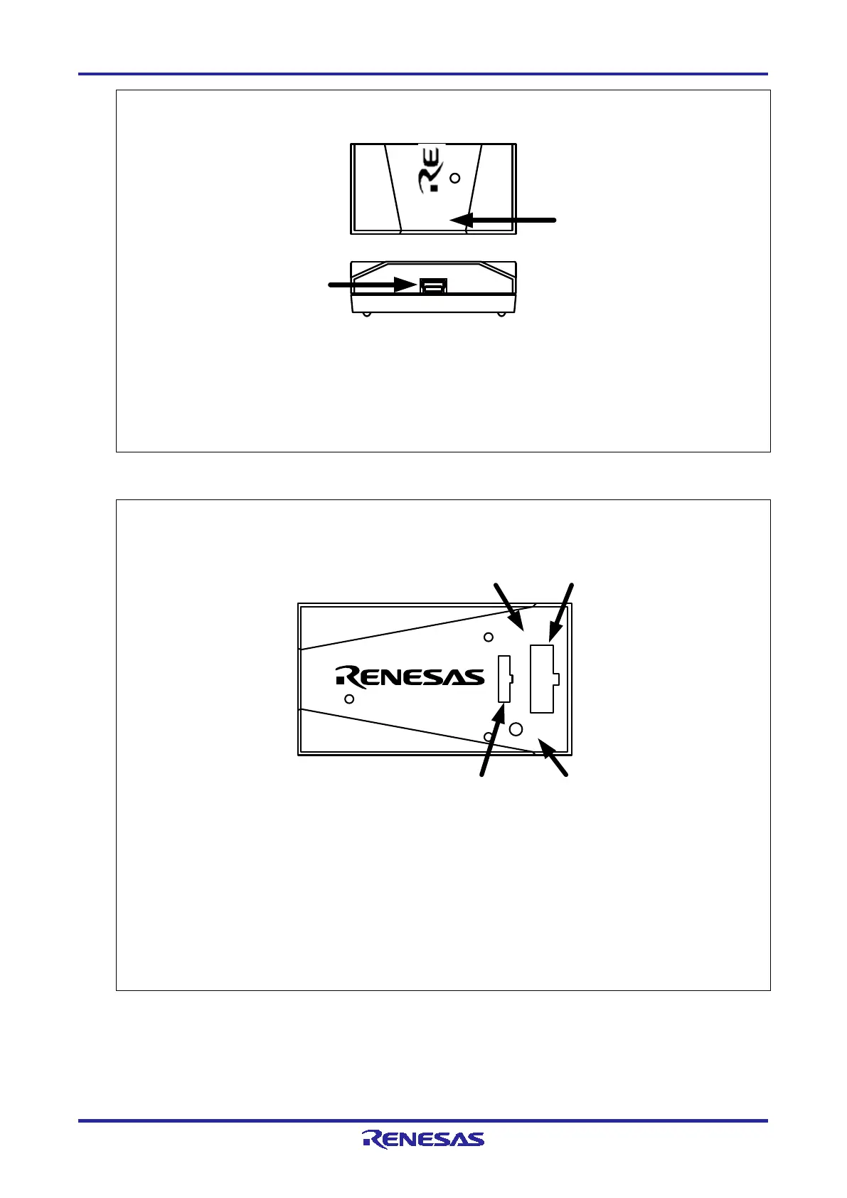
A USB connector for the host machine.
Be sure to connect the provided USB interface cable.
mark
A connector for the host machine is provided at the side of this mark.
Figure 1.4 E2 Lite Host-Side View
E2 Lite
(a) 14-pin user-side
connector
This is for the connection of a 14-pin user-system interface cable.
(b) 20-pin user-side
connector
This is for the connection of a 20-pin to 20-pin user-system interface cable
(separately available) or a 20-pin to 10-pin user-system interface cable.
(c) User-side connector
mark
Marked “USER I/F”.
The connectors for the user-system interface cables is placed to the side of
this mark.
(d) GND This is not used.
Figure 1.5 E2 Lite User-Side Top View
VCC
RESET
ACT
E2 Lite
USER I/F
(
d)(b)
(c)
GND
(a)
USB