Renesas RA Microcontrollers EK-RA4M1 v1 – User's Manual
R20UT4579EU0100 Rev.1.00 Page 9 of 32
Oct.02.19
5. Hardware Layout
5.1 System Block Diagram
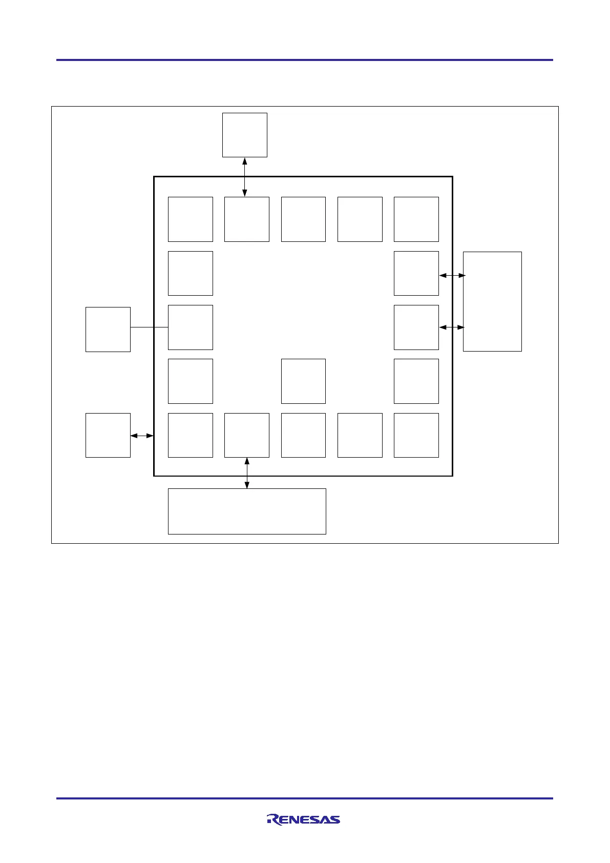
Figure 5. EK-RA4M1 Block Diagram
5.2 Power Requirements
EK-RA4M1 is designed for 3.3 V operation. This also means that 5 V PMOD devices cannot be used
together with the EK-RA4M1 unless they are powered separately.
The total current available from the LDO regulator for all connected circuits is 600 mA or less, depending on
the 5 V power source used.
5.2.1 Power Supply Options
EK-RA4M1 can be powered in several different ways as described in this section.
User
Modules
Config
Jumpers
USB FS
Device
12
M and
32 K
Crystals
3.3V LDO
J-Link
S124
MCU
Status
Two-Color
LED
Power
Measurement
Jumper
Reset Switch
PMOD A,
PMOD B
Main MCU
Pin Headers
User
Push
-Button
User LED
User
Potentiometer
Capacitive
Touch
Button
JTAG Port
J-Link USB
Main MCU
USB FS
Host
Programming or
Debugging PC
Voltage/
Current
Probes
Port Simulation/Simulation
or
Development Daughter Card
Renesas RA Family
RA4M1 MCU Group
Evaluation Kit

 Loading...


