Renesas VUI Reference Solution VOICE-RA2L1 Engineering Manual
VOICE-RA2L1 Engineering Manual Rev.1.0 Page
LED1, user LED, red color
8. Implementation Details
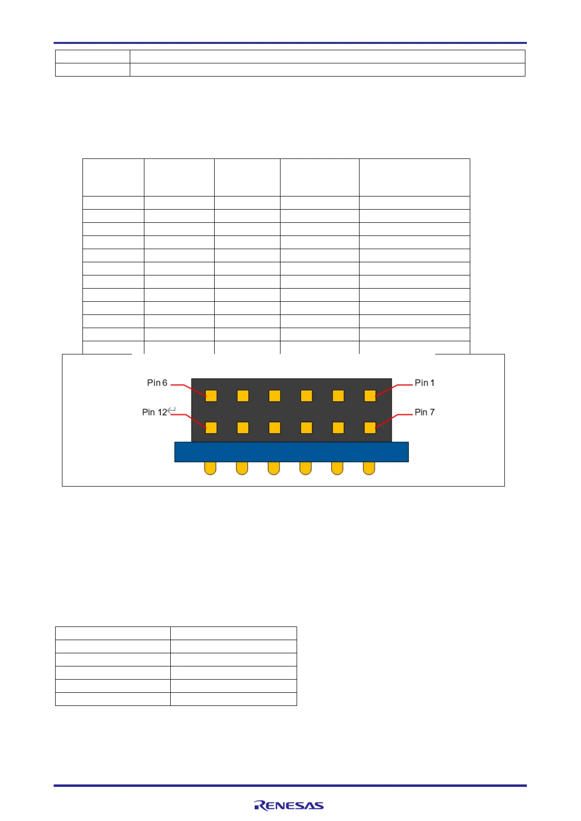
One PMOD type 2A/3A/6A connectors (2x6 pin, dual row, right angle socket) is included. If the RA2L1 SCI9
been configured as Simple I2C, please insert a jumper on header J16 to route SDA signal to PMOD
connector pin 4 for meet PMOD 6A pin definition.
Table 4. PMOD Port Assignments (J15)
PMOD Type
2A Signal
(SPI)
PMOD Type
3A Signal
(UART)
PMOD Type
6A Signal
(I2C)
Figure 4. PMOD connector
8.1 Microphones
This board includes a pair of analog MEMS microphones (M2 & M3, ZillTek ZTS6053). These 2 analog
microphone signals are amplified by Renesas READ2302GSP OPAMP, then fed to RA2L1 ADC channels 0
& 1. One digital I2S MEMS microphone (M1, ZillTek ZTS6672) is also provided, which is connected to
RA2L1 SPI0 channels. The physical distance between the 2 analog microphones is 50mm for support
beamforming applications.
Table 5. Analog MEMS Microphone left channel (M2) Port Assignments
 Loading...


