Renesas VUI Reference Solution VOICE-RA2L1 Engineering Manual
VOICE-RA2L1 Engineering Manual Rev.1.0 Page
of 14
June 2022
6.2 Jumper Settings
Two types of jumpers are provided on the VOICE-RA2L1 board.
1. Traditional pin header jumpers copper jumpers
2. Copper jumpers (trace-cut type and solder bridge type)
6.2.1 Traditional Pin Header Jumpers
These jumpers are traditional small pitch jumpers that require an external shunt to open/close them. The
traditional pin jumpers on the VOICE-RA2L1 board are 2.54mm pitch headers and require compatible
2.54mm shunt jumpers.
Default Jumper Configuration
The following table describes the default settings for each jumper on the VOICE-RA2L1 board. This includes
copper jumpers (Ex designation) and traditional pin jumpers (Jx designation.)
Functional details for many of the listed jumpers may be found in sections associated with each functional
area of the kits.
Table 1. Default Jumper Settings
SCI Boot mode : Close to configures the RA2L1 MCU enter SCI boot
mode, code can be download through J15 PMOD connector.
J3 labeled with “measure current”, it is for measure RA2L1 MCU
current, remove this jumper wire and serial with a current meter to
measure RA2L1 MCU current. The RA2L1 current is around 8.33mA.
Short with a jumper wire to set the on board debug RA4M2 MCU(U8)
in RESET for disable on board debug function.
Short with jumper wire to route I2C SDA signal to J15 PMOD
connector pin 4.
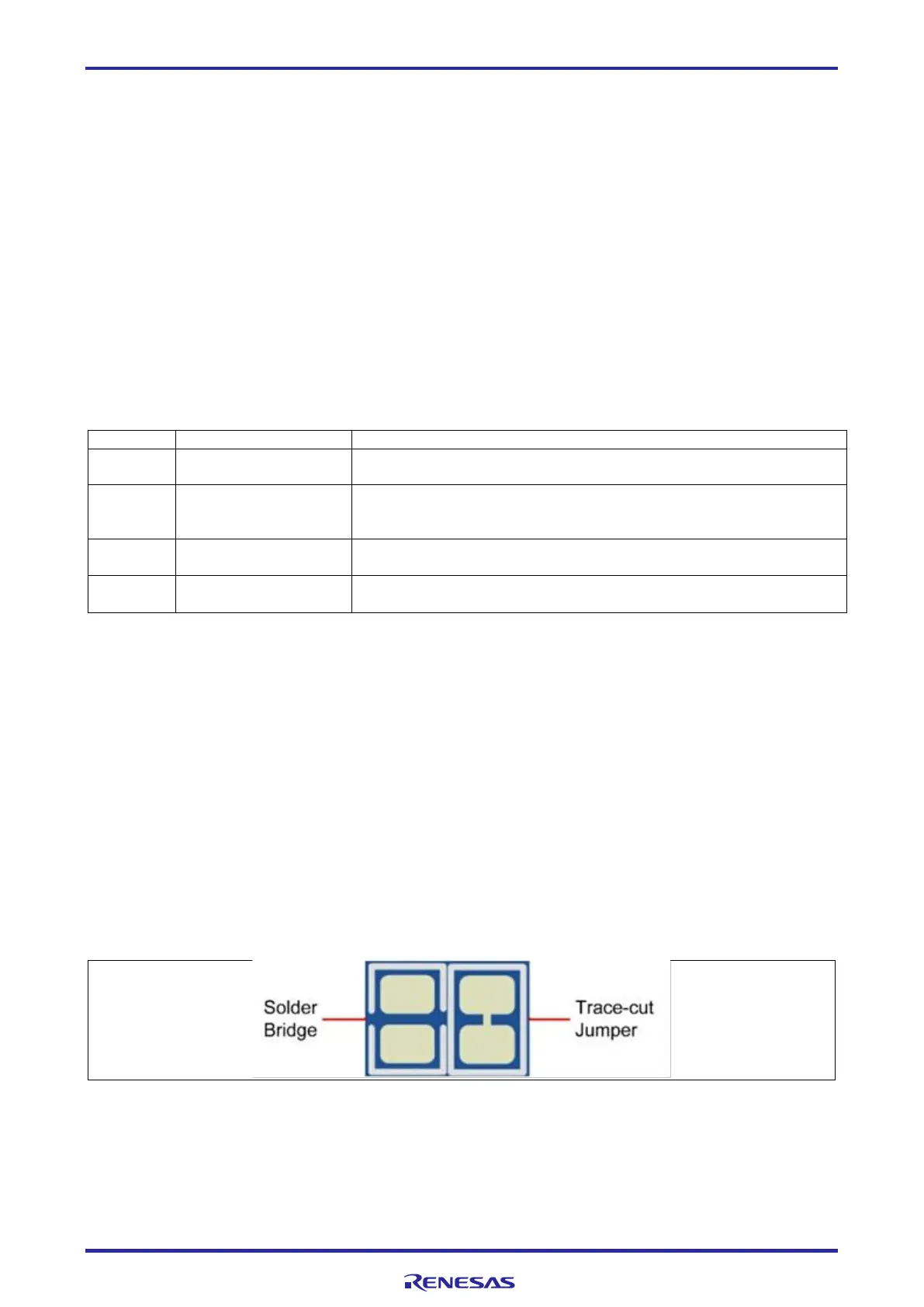
6.2.2 Copper Jumpers
Copper jumpers are of two types, designated trace-cut and solder-bridge.
A trace-cut jumper is provided with a narrow copper trace connecting its pads. The silk screen overlay
printing around a trace-cut jumper is a solid box. To isolate the pads, cut the trace between pads adjacent to
each pad, then remove the connecting copper foil either mechanically or with the assistance of heat. Once
the etched copper trace is removed, the trace-cut jumper is turned into a solder-bridge jumper for any later
changes.
A solder-bridge jumper is provided with two isolated pads that may be joined together by one of three
methods:
⚫ Solder may be applied to both pads to develop a bulge on each and the bulges joined by touching a
soldering iron across the two pads.
⚫ A small wire may be placed across the two pads and soldered in place.
⚫ A SMT resistor, size 0805, 0603, or 0402, may be placed across the two pads and soldered in place. A
zero-ohm resistor shorts the pads together.
For any copper jumper, the connection is considered closed if there is an electrical connection between the
pads (default for trace-cut jumpers.) The connection is considered open if there is no electrical connection
between the pads (default for the solder-bridge jumpers.)
 Loading...


