of 42
May 10, 2017
3.3 Interval Transmission Function
To transmit messages continuously from the same transmit/receive FIFO buffer that is set to transmit mode or
gateway mode
★
, message transmission interval time can be set.
When the use of the transmit/receive FIFO buffer is enabled (the CFE bit of the CFCCk register is “1”), the interval
timer starts counting after the first message is successfully transmitted from the transmit/receive FIFO buffer ((After the
7th bit of EOF in the CAN protocol). After that, when the interval time has elapsed, the next message will be sent and
the interval timer will be reset.
The timing for the interval timer to stop is shown below.
• ・When the use of the transmit/receive FIFO buffer is prohibited (the CFE bit is “0”)
• ・When transitioning to channel reset mode
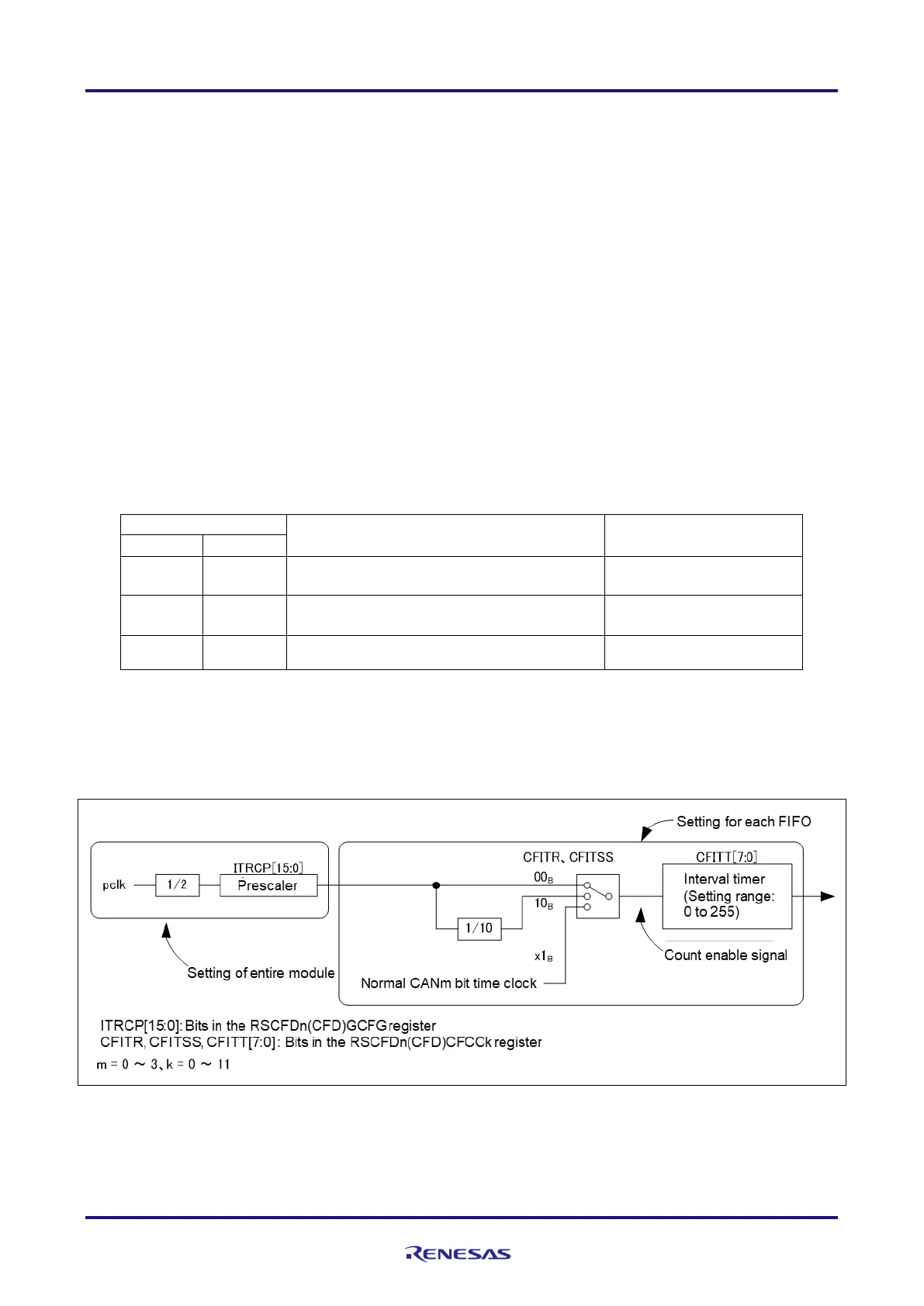
Table 3-1 shows the count source of the interval timer and the calculation formula of the interval timer, Figure 3-5
shows the block diagram of the interval timer, and Figure 3-6 shows the operation example of the interval timer.
Table 3-1 Interval Timer Count Source and Interval Timer Calculation Formula
【Note】 M: Divided value of the clock source of the interval timer for FIFO (set value of the
GCFG.ITRCP [15: 0])
N : Message transmission interval (set value of the CFCCk.CFITT [7: 0])
f
PBA
: pclk frequency
f
CANBIT
: Normal CANm bit time clock frequency
Figure 3-5 Block Diagram of the Interval Timer

 Loading...