EasyManua.ls Logo

Renesas RH850 F1 Series User Manual

Renesas RH850 F1 Series
44 pages
To Next Page IconTo Next Page
Page #1 background imageLoading...
Page #1 background image
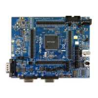
RH850/F1x StarterKit V3
User Manual:
Hardware
RENESAS MCU
RH850 F1x
Series
Y-ASK-RH850F1L-
V3
Y-ASK-RH850F1K-V
3
Y-ASK-RH850F1H-
V3
Y-ASK-RH850F1KM-S4-
V3
Y-ASK-RH850F1KH-D8-
V3
All information contained in these materials, including products and product specifications,
represents information on the product at the time of publication and is subject to change by
Renesas Electronics Corp. without notice. Please review the latest information published by
Renesas Electronics Corp. through various means, including the Renesas Electronics Corp.
website (
http://www.renesas.com).
For updates of the StarterKit software and documentation please check:
http://www.renesas.com/ASK-RH850F1X
32
User Manual
Question and Answer IconNeed help?

Do you have a question about the Renesas RH850 F1 Series and is the answer not in the manual?

Renesas RH850 F1 Series Specifications

General IconGeneral
CoreRH850
Bit Size32-bit
Operating Temperature-40°C to +125°C
CategoryMicrocontroller
SeriesRH850 F1
PackageLQFP

Summary

Notice

Introduction

Cautions

Quick Start Information

3.1 Connector and Jumper Overview

Details signal assignments for J1 and J2 connectors, essential for hardware setup.

3.2 Board Overview RH850/F1L Version [Y-ASK-RH850F1L-V3]

Visual overview of the RH850/F1L StarterKit hardware.

3.3 Board Overview RH850/F1K Version [Y-ASK-RH850F1K-V3]

Visual overview of the RH850/F1K StarterKit hardware.

3.4 Board Overview RH850/F1H Version [Y-ASK-RH850F1H-V3]

Visual overview of the RH850/F1H StarterKit hardware.

3.5 Board Overview RH850/F1KM-S4 Version [Y-ASK-RH850F1KM-S4-V3]

Visual overview of the RH850/F1KM-S4 StarterKit hardware.

3.6 Board Overview RH850/F1KH-D8 Version [Y-ASK-RH850F1KH-D8-V3]

Visual overview of the RH850/F1KH-D8 StarterKit hardware.

StarterKit Hardware

4.1 StarterKit Functions

Outlines the various functions and features integrated into the StarterKit hardware.

4.2 Functional Areas

Describes the different areas and components on the StarterKit board.

4.2.3 LEDs

Details the different types of LEDs (RGB, indicator, power supply) on the board.

4.2.8 Serial Communication Interfaces

Covers the RS232, LIN, CAN, and Ethernet communication interfaces.

4.2.9 On-chip Debug and Flash Programming Connector

Information on the connector for debugging and programming tools.

Development Tools

5.1 E1 On-Chip Debug Emulator

Powerful debugging tool with flash programming functions for Renesas microcontrollers.

5.2 Development Software

Lists the development software tools included in the StarterKit package.

Example Software

6.1 StartUp Test

Describes the initial startup test procedure and its verification steps.

6.2 Mode 1 Operation

Details the first operational mode, involving LEDs and potentiometer interaction.

6.3 Mode 2 Operation

Details the second operational mode, with blinking LEDs and encoder interaction.

6.4 StandBy Mode

Explains the standby mode for low power consumption and wake-up procedures.

6.5 Webserver Application

Covers the webserver functionality for monitoring and control via Ethernet.

Component Placement and Schematics

7.1 Component Placement Guide

Visual guide to the physical placement of components on the StarterKit board.

7.2 Schematics Overview

Provides detailed circuit schematics for different StarterKit versions.

Revision History