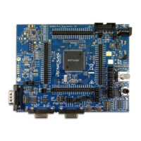
RH850/F1x StarterKit V3 User Manual
R01UH0724ED0120 Page 28
January 2018
4.2.9 On-chip Debug and Flash Programming Connector
Connector CN3 is provided to allow the connection of microcontroller debug and flash
programming tools. Connector CN3 is a 14 pin, 0.1” pin pitch connector. The pinout of this
connector supports the Renesas E1 On-chip debug emulator. For more information about E1,
please see Chapter 5.1 E1 On-Chip Debug Emulator [R0E000010KCE00].
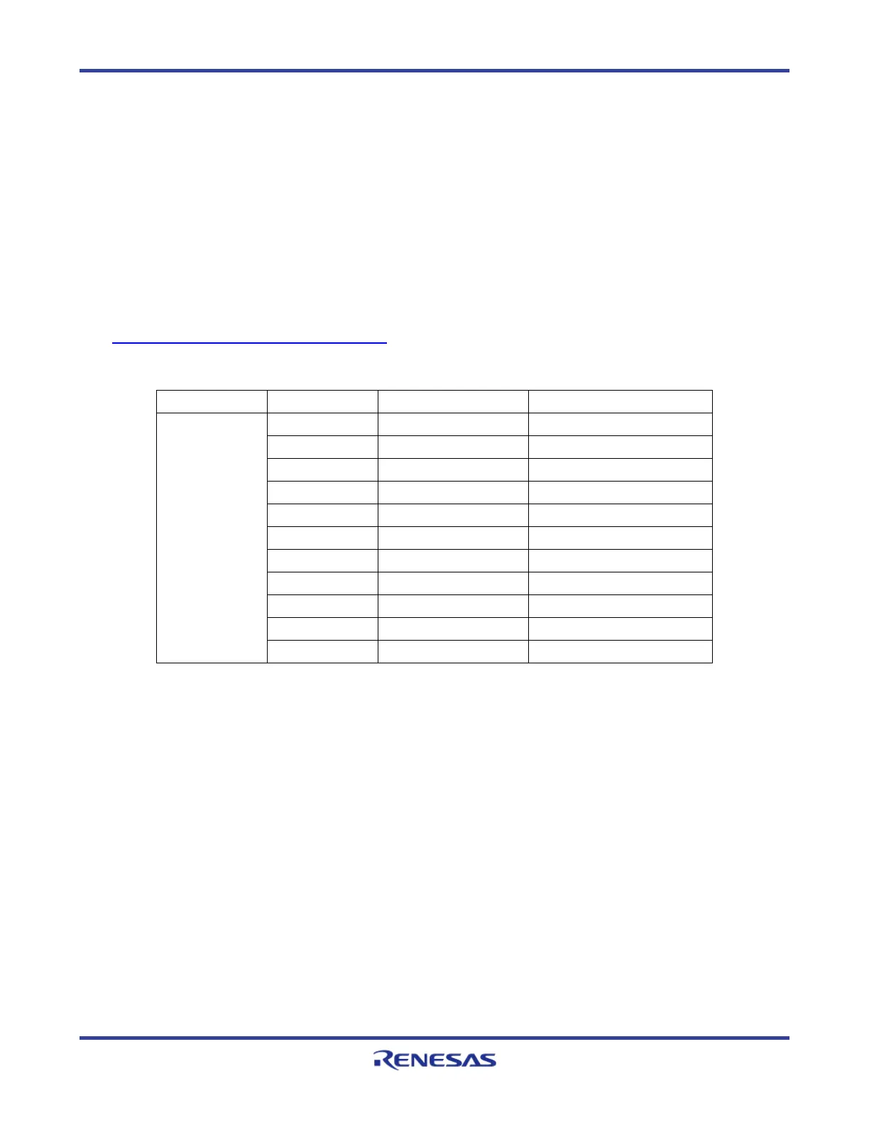
4.2.10 OLED Board (optional)
The StarterKit offers a pin header to optionally connect an external display to the board. For
example following OLED Display with microSD card holder is compatible to the connector:
https://www.adafruit.com/products/1673
Header Pin number signal Note
Display
1 MOSI P11_2
2 SCK P11_3
3 DC(data command) P11_0
4 RESET P10_12
5 OLEDCS P11_15
6 SDCS P12_1
7 MISO P11_4
8 CD(card detected) P11_5
9 3Vo AP0_4
10 Vin VDD_5V
11 GND GND
Table 34. OLED header (optional)
 Loading...