RH850/F1x StarterKit V3 User Manual
R01UH0724ED0120 Page 22
January 2018
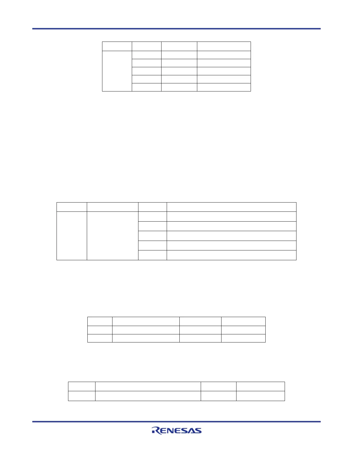
Table 15. Blue LED Circle Signals
4.2.4 Digital inputs for Low Power Sampler (LPS)
Eight digital input signals, which are generated by a DIP switch array (S3), are provided to trigger
the microcontroller’s Low Power Sampler. The input signals are connected to the microcontroller
via 8 to 1 Multiplexer (IC4). When the DIP switches (S3) are changed during low power mode
(DeepSTOP mode), the microcontroller will wake up.
Please use the following jumper configuration to connect the DIP Switch and multiplexer to the
microcontroller
J9 Digital LPS input
to MCU
connector
1 – 2
DIN ↔ P8_1
3 – 4
SELDP0 ↔P0_4
5 – 6
SELDP1 ↔ P0_5
7 – 8
SELDP2 ↔ P0_6
9 – 10
DPO ↔ P0_0
Table 16. LPS Jumper Configuration
4.2.5 Pushbutton Switches
Two pushbutton switches (S1and S2) are provided to allow the switching of microcontroller input
port states. The switches are active low and normally open.
Table 17. Pushbutton Switch Signals
Please use the following jumper configuration to connect the interrupt pushbutton switch (S1) to
the microcontroller.
J16 Interrupt Button to MCU connector 1-2
Button ↔ P0_9
Table 18. Interrupt Pushbutton Jumper Configuration
 Loading...