RH850/F1x StarterKit V3 User Manual
R01UH0724ED0120 Page 21
January 2018
connected to the A/D converter of the microcontroller to evaluate the LED drive state. The LED
PWM signals are active high.
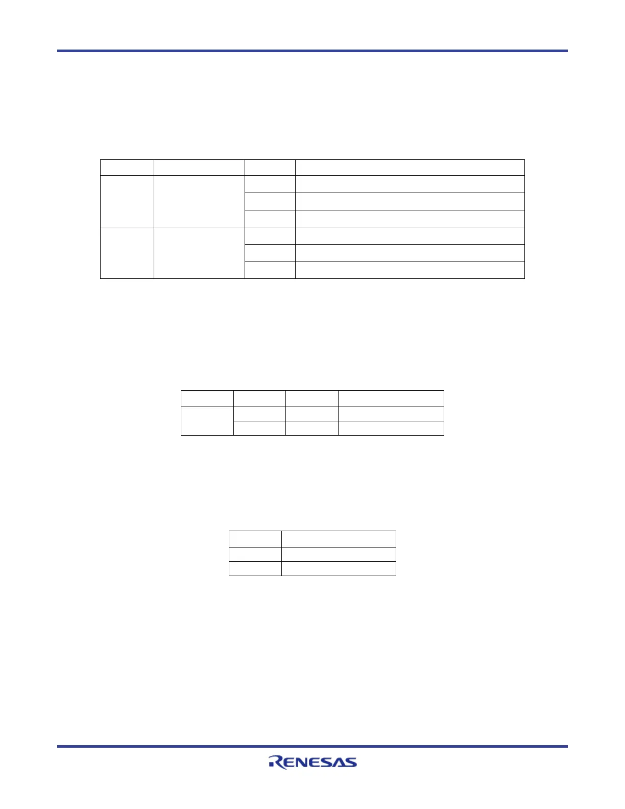
Please use the following jumper configuration to activate the full RGB LED functionality:
J20 RGB LED PWM
connector
1-2
Red PWM channel↔ P20_1
3-4
Green PWM channel ↔ P20_2
5-6
Blue PWM channel ↔ P20_3
J13 RGB LED
feedback
connector
1-2
Red LED feedback channel ↔ AP0_1
3-4
Green LED feedback channel ↔ AP0_2
5-6
Blue LED feedback channel ↔ AP0_3
Table 12. White RGB Signals Configuration
4.2.3.2 Green Indicator LEDs
Two green low power LEDs (LED1 and LED2) are provided to allow visual observation of
microcontroller output port states. The LED signals are active high.
Jumper Setting LED Device Port
Table 13. Green Indicator LED Signals
4.2.3.3 Blue Power Supply LEDs
Two blue LEDs (D5 and D6) are provided to allow visual observation of the power supply status.
LED Note
Table 14. Blue Power Supply LED Signals
4.2.3.4 Blue LED Circle
Sixteen blue LEDs are driven by the TLC5925, which can controlled by the SPI command to change
the output states.
 Loading...