The Renishaw RESOLUTE Functional Safety Siemens DRIVE-CLiQ encoder system is a safety-related control system designed for use in various industrial applications. It is certified to Safety Integrity Level (SIL) and Performance Level (PL) standards, specifically SIL2 with HFT = 0 (1oo1) and Category 3, PLd according to IEC 61508-1:2010, IEC 61508-2:2010, IEC 61508-3:2010, IEC 61800-5-2:2016, ISO 13849-1:2015, ISO 13849-2:2012, and IEC 61784-3:2016. The system is not to be used in environments with explosive atmospheres or by medical devices.
Function Description
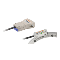
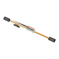
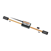
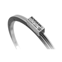
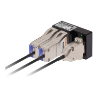
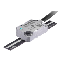
The RESOLUTE Functional Safety Siemens DRIVE-CLiQ encoder system provides precise position and motion feedback for safety-related control systems. It comprises RESOLUTE Functional Safety readhead(s) with integral cables, a DRIVE-CLiQ interface (available for single and dual readhead configurations), and various scale options including taper mounted RESA30 'A' section rings, interference mounted RESA30 'A' section/'B' section rings, REXA30 rings, RTLA30-S tape scale, RTLA30 tape scale with FASTRACK carrier, and RSLA30/RELA30 linear scales (adhesive mount only). The system is designed to report errors to the system manufacturer's evaluation unit, which is responsible for implementing appropriate actions.
The system supports several safety sub-functions defined by IEC 61800-5-2, including:
- Safe stop 1 (SS1) and Safe stop 2 (SS2)
- Safe operating stop (SOS)
- Safe limited acceleration (SLA) ≤ 500 m/s²
- Safe acceleration range (SAR) ≤ 500 m/s²
- Safe limited speed (SLS)¹ ≤ 100 m/s
- Safe speed range (SSR)¹ ≤ 100 m/s
- Safely limited position (SLP)
- Safely limited increment (SLI)
- Safe direction (SDI)
- Safe speed monitor (SSM)¹ ≤ 100 m/s
The maximum request rate supported is 16 kHz. The system can support various maximum scale lengths depending on the bit position word: 17.18 m with a 34-bit position word and 13.42 m with a 28-bit position word. Electrical errors are detected if linear systems exceed 600 µm or rotary systems exceed 1.5°. Mechanical errors are detected if linear systems exceed 1 mm or rotary systems exceed 2.5°.
Important Technical Specifications
- Safety Integrity Level: 2 (Single readhead system), 2 (Dual readhead system)
- Random Hardware Failures (per hour):
- Single readhead: λDU = 6.86 x 10⁻⁹, λDD = 1.07 x 10⁻⁸, λSD = 9.64 x 10⁻⁸, λS = 1.07 x 10⁻⁷
- Dual readhead: λDU = 1.26 x 10⁻⁸, λDD = 1.95 x 10⁻⁸, λSD = 1.76 x 10⁻⁷, λS = 1.95 x 10⁻⁷
- PFH (per hour): Not applicable due to continuous use
- Architectural Constraints: Type B, HFT = 0, SFF = 94%, Route 1H
- Systematic capability: SC2
- Demand mode: Continuous
- Proof test interval: Not required for continuous demand mode
- MTTF (years): 106 (Single readhead system), 58 (Dual readhead system)
- Diagnostic coverage: Medium (90%)
- Category: 3
- Performance level: d
- Lifetime/Replacement limits: 20 years
- Power Supply: 24V (DRIVE-CLiQ network), 4.3 W maximum
- Interface over voltage protection: -36 V to +36 V
- Temperature:
- Storage: -20 °C to +70 °C
- Installation: 20 ±5 °C
- Operating (readhead): 0 °C to +80 °C
- Operating (interface): 0 °C to +55 °C
- Humidity: 95% relative humidity (non-condensing) to IEC 60068-2-78
- Sealing: IP64 (system), IP67 (interface)
- Environment protection: Protection class III, Pollution degree II, Altitude 2000 m
- Acceleration: 500 m/s², 3 axes (Operating readhead)
- Shock: 500 m/s², 11 ms, ½ sine, 3 axes (Non-operating readhead)
- Maximum acceleration of scale with respect to readhead: 2000 m/s²
- Vibration: 300 m/s² max @ 55 Hz to 2000 Hz, 3 axes (Operating readhead), 100 m/s² max @ 55 Hz to 2000 Hz, 3 axes (Operating interface)
- Mass: 18 g (readhead), 32 g (readhead cable), 218 g (interface)
- Readhead cable: 7 core, tinned and annealed copper, 28 AWG, Single-shielded, outside diameter 4.7 ±0.2 mm, Flex life >40 x 10⁶ cycles at 20 mm bend radius, 10 m maximum length (refer to Siemens DRIVE-CLiQ specifications for maximum cable length from interface to controller), UL recognised component.
Usage Features
- Installation: The installation process involves mounting the readhead(s) and scale(s) according to specific drawings and instructions provided in the manual. Different mounting options are available for rotary rings (taper mount, interference fit, flange mount) and linear scales (adhesive mount, FASTRACK carrier). Proper cleaning of surfaces with approved solvents (N-heptane, propan-2-ol, acetone, methylated spirits) is crucial for optimal performance.
- Cutting Scales: RTLA30-S and RTLA30/FASTRACK scales can be cut to length using a guillotine or shears. Specific instructions are provided to ensure correct orientation and prevent damage.
- Applying Scales: Adhesive-mounted scales (RELA30/RSLA30, RTLA30-S, RTLA30/FASTRACK) require careful application of epoxy and proper alignment using dowels or ledges.
- Datum Clamp: A datum clamp is used to fix the RTLA30-S scale rigidly to the substrate at the chosen location. Loctite® 435™ adhesive is used for secure attachment.
- Readhead Mounting and Alignment: Readheads must be mounted on a flat surface and adjusted to conform to installation tolerances, rideheight, and to prevent deflection or vibration. The recommended screw type is M3 x 0.5 mm, with a thread engagement of 6 mm and a tightening torque of 0.9 Nm to 1.1 Nm.
- System Configuration: The system supports single and dual readhead configurations, connecting to a Siemens controller via a DRIVE-CLiQ interface.
- Electrical Connections: Detailed wiring diagrams are provided for RESOLUTE output signals and DRIVE-CLiQ interface output, including pin assignments, wire colours, and functions.
- Adjusting Rings: For REXA30 rings, a Dial Test Indicator (DTI) is used to measure and adjust run-out to within 10 µm TIR.
Maintenance Features
- Evaluation Unit Monitoring: The evaluation unit continuously monitors the error condition of the RESOLUTE Functional Safety Siemens DRIVE-CLiQ encoder system. A persistent fault condition may indicate a hardware failure of the RESOLUTE Functional Safety Siemens DRIVE-CLiQ encoder system or an installation problem.
- Maintenance and Cleaning: Regular maintenance checks are required, including checking for tightened bracket screws, damaged cables, and contaminated scales.
- Cleaning: Renishaw scale wipes (A-9523-4040) or a clean, dry, lint-free cloth can be used with propan-2-ol (iso-propyl alcohol) or N-heptane. Acetone, chlorinated solvents, and methylated spirits are not recommended for cleaning the readhead and DRIVE-CLiQ interface.
- Repair: Repair of system parts should only be done with Renishaw's approval. Damaged parts should be returned to Renishaw for further analysis.
- Proof Testing: The system manufacturer is responsible for defining any proof testing. The encoder supports continuous demand use.
The system is designed for long-term reliability with a lifetime/replacement limit of 20 years.