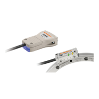
Remote LED driver outputs
JST connector version allows for remote
monitoring of readhead status.
8
RGH24 RGS20 installation guide
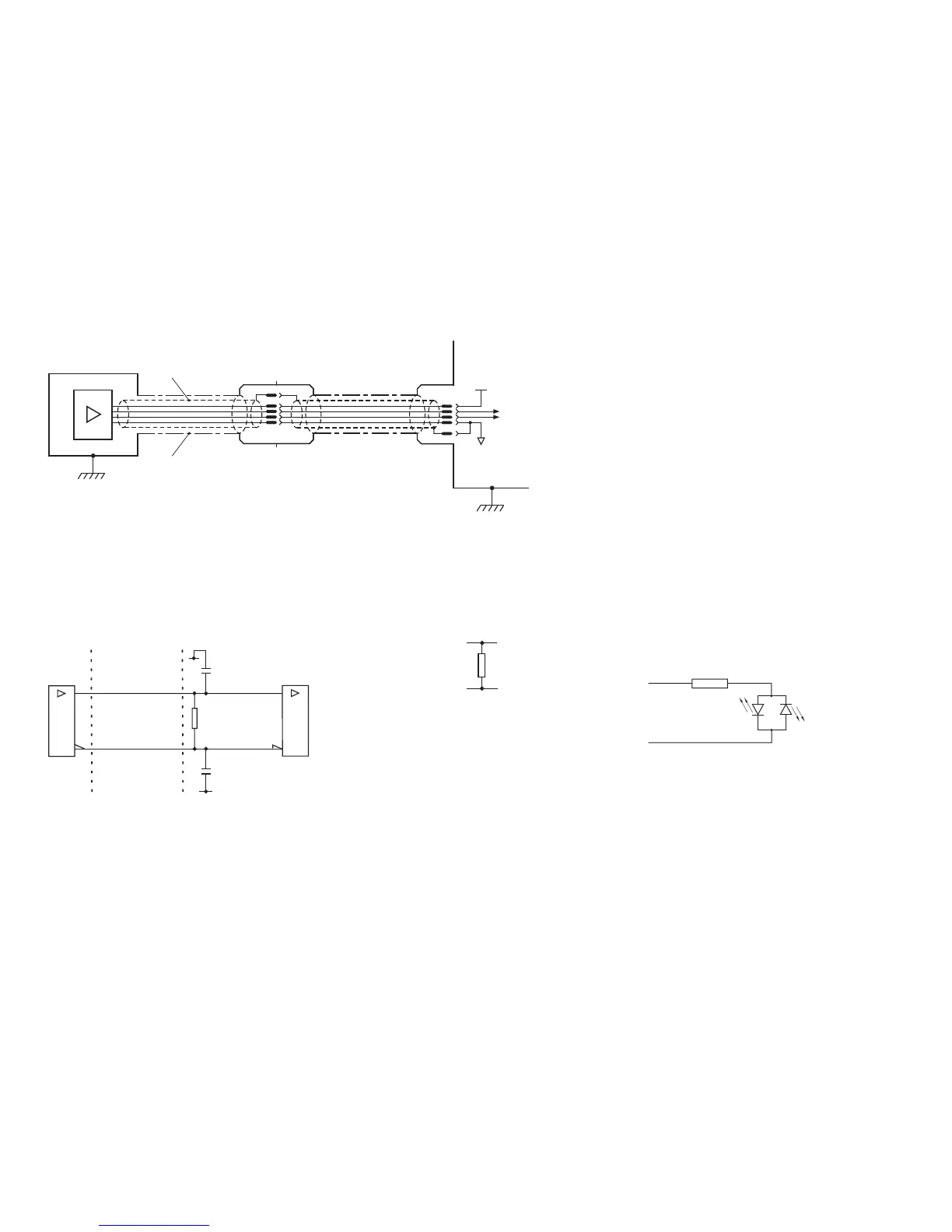
Electrical connections
Grounding and shielding
*Maximum extension cable length
RGH24B - 100 m, RGH24D, X and Z - 50 m, RGH24W , Y, H, I and O - 20 m
RGH24
Customer
electronics
Extension cable*
Inner shield
Outer shield
Output
signals
0 V
5 V
IMPORTANT: The outer shield should be connected to the machine earth (Field Ground). The inner shield should be connected
to 0 V. Care should be taken to ensure that the inner and outer shields are insulated from each other. If the inner and outer shields
are connected together, this will cause a short between 0 V and earth, which could cause electrical noise issues.
Recommended signal termination
Digital outputs - RGH24D, X, Z, W, Y, H, I and O
Analogue output - RGH24B
V
0
V
1
V
2
+
V
0
V
1
V
2
-
120R
Standard RS422A line receiver circuitry
Capacitors recommended for improved noise immunity.
Customer
electronics
120R
A B Z Q-
Cable Z
0
= 120R
Readhead
A B Z Q+
0 V
0 V
220 pF
220 pF
Green
Red
Red/Green
LED
150R
+
–
Green
Red

 Loading...