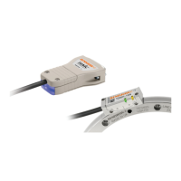
RGS20 scale installation drawing (with reference mark actuator)
Dimensions and tolerances in mm
4
RGH24 RGS20 installation guide
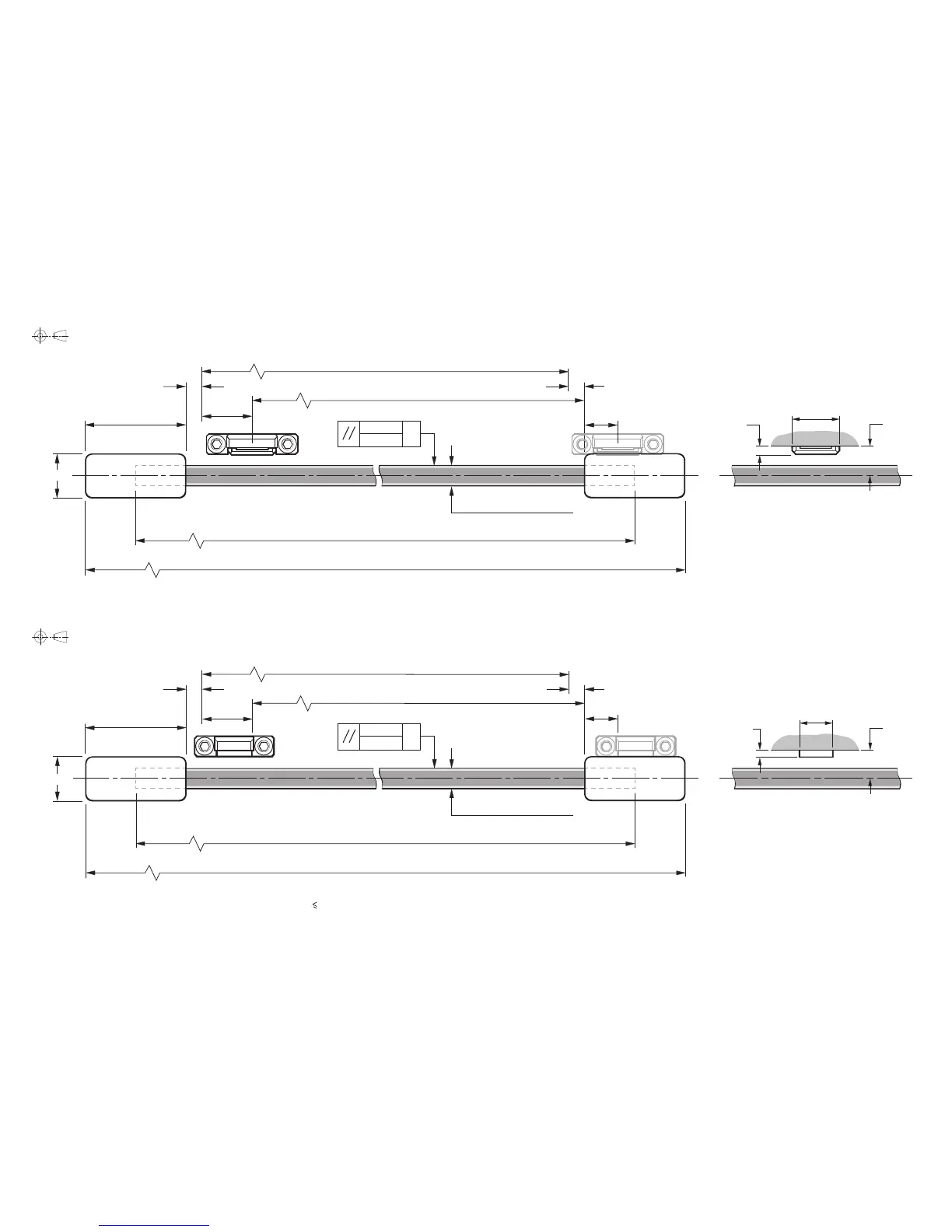
NOTE: The surface roughness of the scale mounting surface must be 3.2 Ra. The parallelism of the scale surface to the axis of motion (readhead rideheight variation) must be within 0.05 mm.
Measuring length (ML)
Overall length (ML + 70)
<10
6 (RGS20-S) 6.3 (RGS20-P)
Scale length (ML + 40)
10
2
8.5
14
8.72.2
Measuring length (ML)
Reference mark actuator position range
Limit switch actuator position range
0.5
0.2/100
F = axis of motion
F
0.5
0.2/100
F = axis of motion
F
6 (RGS20-S) 6.3 (RGS20-P)
Scale length (ML + 40)
Overall length (ML + 70)
>15
30
13
>5
>15
30
>5
13
Bolted reference mark actuator shown
(A-9541-0037)
Bolted limit switch actuator shown
(A-9541-0040)
Optional epoxy mounted reference mark actuator
(A-9531-0250)
<10
>5
>5
Optional epoxy mounted limit switch actuator
(A-9531-0251)
RGS20 scale installation drawing (with limit switch actuator)
Dimensions and tolerances in mm

 Loading...