3
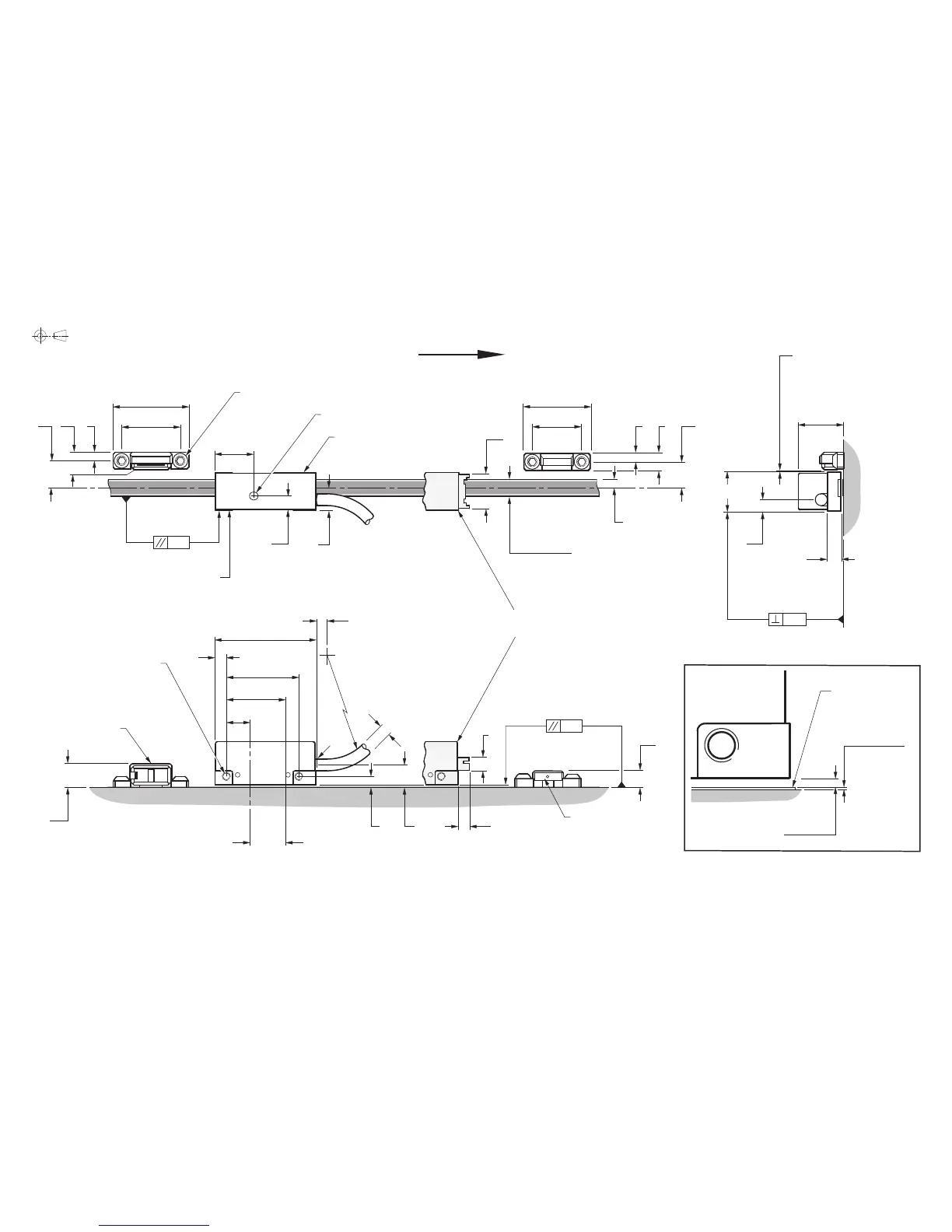
RGH24 readhead installation drawing
Dimensions and tolerances in mm
RGH24 RGS20 installation guide
*
Dimensions measured from substrate.
=
Required nominal 0.8 gap can be set using blue readhead spacer (supplied) positioned between readhead and actuator when positioning/fixing the actuator.
Rideheight
0.8 ±0.1
9.5
6.2
27
21
0.6
0.3
(Yaw Tol. ±0.5°)
R>20 Dynamic bend radius
R>10 Static bend radius
(Pitch Tol. ± 1°)
Fixing screws
M3 x 0.5 x 8
6
3
6 (RGS20-S)
6.3 (RGS20-P)
36
26
21.1
>4
4
8.5
8.5
*
A
Reference mark actuator
(A-9541-0037)
4
*
8
*
2 Mounting holes
M3 x 0.5 through
Set-up LED
5
4.3
17
JST connector
version
12.8
5.5
Arrow indicates forward direction
of readhead relative to scale
Limit switch
actuator
(A-9541-0040)
Readhead to
scale clearance
Detail A
Scale surface
11.9
8
23
9.3
Alternative
mounting face
6.4
*
(Roll Tol. ± 1°)
0.09
3.8
13.5
15.8
*
4.8
(Extent of mounting faces)
Mounting face
3
3
Scale thickness:
0.2 (RGS20-S)
0.3 (RGS20-P)
Reference mark sensor/
limit switch sensor position
Optical centreline
( )
0.8 -0.1
+0.2
See note
=
Ø4.4 max

 Loading...