6
TONiC RESM20 angle encoder system installation guide
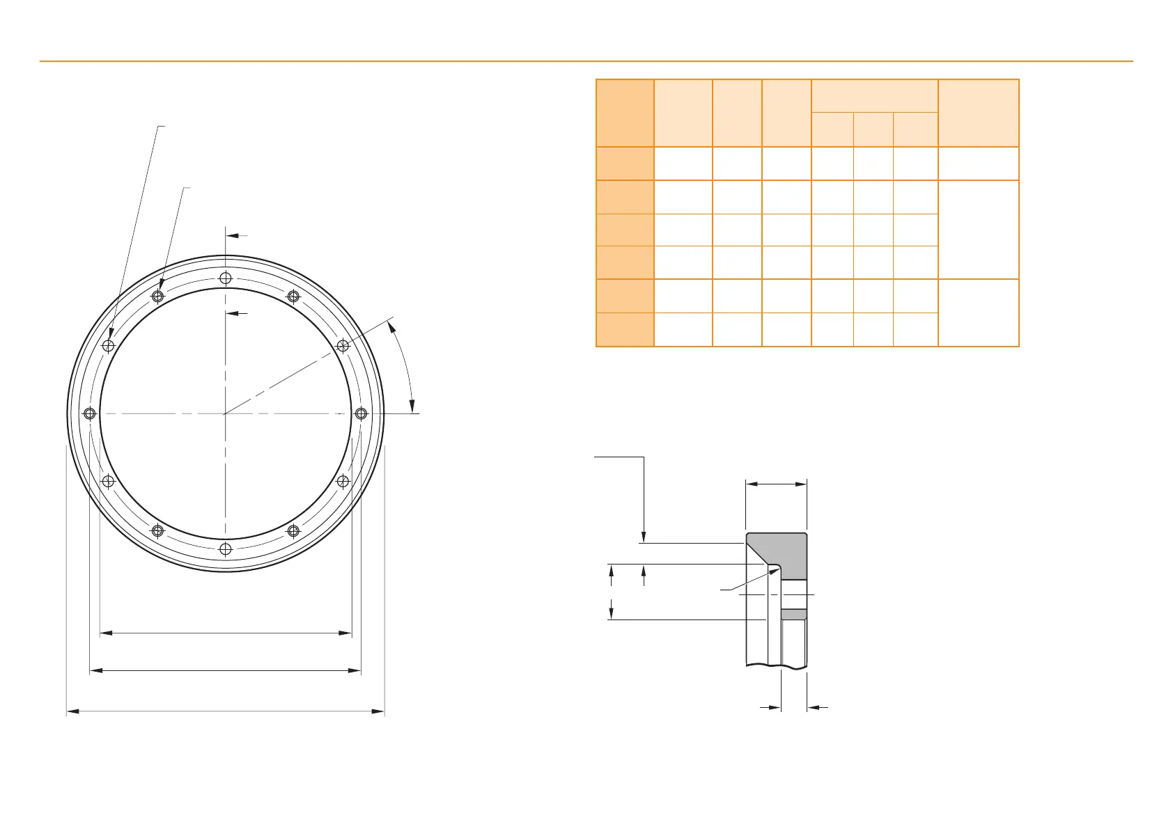
RESM20 installation drawing (‘B’ section)
N holes equally spaced on PCD ØDH Ø3.5 through
N holes equally spaced on PCD ØDH M3 × 0.5 through
A
θ
A
ØDI
ØDH
ØDO
NOTE: θ is the angle between one tapped hole and the adjacent clearance hole.
The angle between two clearance holes is 2θ.
Section A–A
Nominal
external
diameter
(mm)
Line
count
DO
(mm)
DI
(mm)
Mounting holes Readhead
model
DH
(mm)
N
θ
52 8 192
52.20
52.10
32.04
32.00
38 6 30° T2021
75 11 840
75.40
75.30
55.04
55.00
61 6 30°
T2011100 15 744
100.30
100.20
80.04
80.00
86 6 30°
115 18 000
114.70
114.50
95.04
95.00
101 6 30°
150 23 600
150.40
150.20
130.04
130.00
136 9 20°
T2001
200 31 488
200.40
200.20
180.04
180.00
186 12 15°
7
2.5 × 45°
3
R0.5
6.5
Dimensions and tolerances in mm
 Loading...