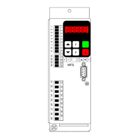
REOVIB MFS 268
Operating Instructions EtherNet/IP - Programming
6
5.1 Programming for the Bus operation
In normal operation the set point for Amplitude (throughout/feed rate) and the digital control signals, such
as enable are set across the interface. The actual voltage/current values and unit status (ready or fault)
are fed back. All data words are within the range 0…FFFF H.
The following communication words are given in bit form.
5.1.1 Send to Controller
H-Byte L-Byte
0000 H (reserved)
15 14 13
9 8 7 6 5 4 3 2 1 0
H-Byte L-Byte
Set point 1, 16-Bit 100 % = FFFF H
15 14 13
9 8 7 6 5 4 3 2 1 0
H-Byte L-Byte
9 8 7 6 5 4 3 2 1 0
H-Byte L-Byte
Control - word
Bit = „1“ = Function ON
All unused bits MUST be set to `0`
15 14 13
9 8 7 6 5 4 3 2 1 0
0 Mode bit
0
0
0
0
0
0
0
0
0
0
0
0
0 Enable
0
0
Control information (unit specific)
5.1.2 Reply from Controller
H-Byte L-Byte
xxxx H (undefined)
15 14 13
9 8 7 6 5 4 3 2 1 0
H-Byte L-Byte
Feed back actual acceleration
16 Bit 100% = 8000H
15 14 13
9 8 7 6 5 4 3 2 1 0
H-Byte L-Byte
Feed back actual output current,
16 Bit 100% = 8000H (in % von I-nom)
15 14 13
9 8 7 6 5 4 3 2 1 0
H-Byte L-Byte
Status - Word
X = Not defined
Bit = „1“ = Function ON
15 14 13
9 8 7 6 5 4 3 2 1 0
Status - Code
ERROR - Code
Status information
Unit specific
00
A5 (H)
57 (H)
58 (H)
02 (H)
0C (H)
05 (H)
C0 (H)
Unit not responding
Unit ready
ERROR Peak
ERROR OC
ERROR OL
ERROR ACC
ERROR OU
Acknowledge
Parameter mode
Status, actual acceleration and actual output current are received.
0 = Normal operation
1 = Parameter operation
Enable - bit
OFF – Bit
Acknowledge
 Loading...