1
3
2
backwards
forward
SET
(selection / adjustment mode)
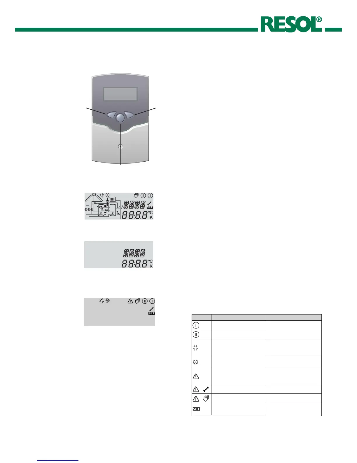
The system monitoring display consists of 3 blocks: channel
display, tool bar and system screen (active arrange-
ment).
The channel display consists of two lines. The upper line
is an alpha-numeric 16-segment display (text display) for
displaying channel names and menu items. In the lower
7-segment display, the channel values and the adjustment
parameters are displayed.
Temperatures and temperature differences are indicated
in°C or K respectively.
2.2.1 Channel display
channel display
2.2.2 Tool bar
The additional symbols in the tool bar indicate the actual
system status.
tool bar
2. Operation and function
2.1 Buttons for adjustment
The controller is operated via the 3 push buttons below the
display. The forward-button (1) is used for scrolling forward
through the display menu or to increase the adjustment va-
lues. The backward-button (2) is similarly used for scrolling
backwards and reducing values.
In order to access the adjustment mode, scroll down in the
diplay menu and press the forward button (1) for approx.
2 seconds after you have reached the last diplay item. If an
adjustment value is shown on the display, the „SEt“ icon
is displayed. Now, you can access the adjustment mode by
using button 3.
• Press buttons 1 and 2 in order to select a channel
• Briey press button 3, „SEt“ will ash
• Adjust the value by pressing buttons 1 and 2
• Briey press buttons 3, so that „SEt“ permanently
appears, the adjusted value will be saved.
2.2 System monitoring display
Complete Monitoring-Display
Symbol standard flashing
relay 1 active
relay 2 active
store maximum limitation
active / maximum store
temperature exceeded
collector cooling function or
recooling function active
antifreeze- function activated
collector minimum limitation
or antifreeze function active
collector emergency shutdown
or store emergency shutdown
active
+
sensor defect
+
manual operation active
SET-mode, change of adjust-
ment value is possible

 Loading...