D e lt a S o l
®
C/4
© RESOL 11103 deltasol_c/4.monen.indd
5 |
1.2 Electrical connection
The power supply to the controller must be carried out via
an external power switch (last step!) and the supply voltage
must be 100 ... 240 V~ (50 ... 60 Hz). Flexible cables must be
attached to the housing with the enclosed strain relief and
the corresponding screws.
The controller is equipped with 2 relays to which loads
such as pumps, valves etc. can be connected:
• Relay 1
18 = conductor R1
17 = neutral conductor N
13 = ground clamp
• Relay 2
16 = conductor R2
15 = neutral conductor N
14 = ground clamp
The temperature sensors (S1 to S4) have to be connec-
ted to the following terminals (either polarity):
1 / 2 = sensor 1 (e. g. sensor collector 1)
3 / 4 = sensor 2 (e. g. sensor store 1)
5 / 6 = Sensor 3 (temperature sensor S3)
7 / 8 = sensor 4 (e. g. sensor store TRF)
The mains connection is carried out at the following
terminals:
19 = neutral conductor N
20 = conductor L
12 = ground clamp
The controller is equipped with the RESOL VBus
®
for
data transfer with and energy supply to external modules.
The connection is carried out at the two terminals 9
and 10 marked “VBus
®
“ (either polarity). One or more
RESOL VBus
®
modules can be connected via this data bus:
• RESOL calorimeter
• RESOL large display / Smart Display
• RESOL datalogger
Electrostatic discharge can cause damage of electronic
components!
High-voltage components!
Note:
One of the relays is a semiconductor relay for pump speed
control. A minimum load of 20 W (power consumption of
the load) is required for faultless function. The capacitor
from th e accessory bag must be connected in parallel to
the respective relay output if it feeds auxiliary relays, motor
valves, etc.
Attention: The minimum pump speed must be set to 100%
when auxiliary relays or valves are connected.
VBus
9
10
1 (1) A (100 ... 240) V~
1 (1) A (100 ... 240) V~
R1
R2
IP 20
T2A
100 ... 240 V~
50-60 Hz
mains terminals
fuse
load terminals
sensor terminals
ground terminals
S1
S2
S4 / TRF
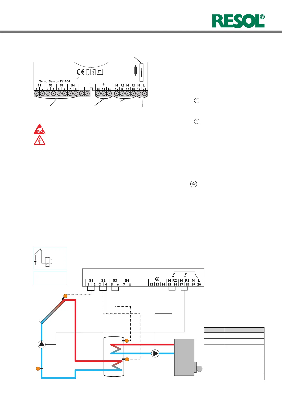
1.2.1 Terminal allocation Arr1
Standard solar system with 1 store, 1 pump and 3
sensors. Sensor S4 / TRF can optionnally be used for heat
quantity measurement.
R1
ARR 1
S3
Symbol Description
S1 collector sensor
S2 store base sensor
S3 store top sensor
(optional)
S4 / TRF sensor for heat
quantity measure-
ment (optional)
R1
solar pump
 Loading...