Display Description (long text)
MWh Heat quantity MWh
BLPR Blocking protection relay 1
BLPR2 Blocking protection relay 2
BLPR3 Blocking protection relay 3
INIT Initialisation drainback
FLLT Filling time drainback
STAB Stabilisation drainback
TDIS Disinfection temperature
CDIS Countdown thermal disinfection
DDIS Disinfection period
SDIS Starting delay
TIME
DATE
6 Balance values
The balance value menu indicates the balance values.
Display Description
h R1 Operating hours relay 1
h R2 Operating hours relay 2
h R3 Operating hours relay 3
h R4 Operating hours relay 4
DAYS Operating days of the controller (cannot be set back to zero)
MAXS1 Maximum temperature sensor 1
MINS1 Minimum temperature sensor 1
MAXS2 Maximum temperature sensor 2
MINS2 Minimum temperature sensor 2
MAXS3 Maximum temperature sensor 3
MINS3 Minimum temperature sensor 3
MAXS4 Maximum temperature sensor 4
MINS4 Minimum temperature sensor 4
MAXS5 Maximum temperature sensor 5
MINS5 Minimum temperature sensor 5
MAXS6 Maximum temperature sensor 6
MINS6 Minimum temperature sensor 6
7 Commissioning
When the hydraulic system is lled and ready for operation, connect the controller
to the mains.
The controller runs an initialisation phase in which all symbols are indicated in the
display. The Lightwheel
®
ashes red.
When the controller is commissioned or when it is reset, it will run a commis-
sioning menu after the initialisation phase. The commissioning menu leads the user
through the most important adjustment channels needed for operating the system.
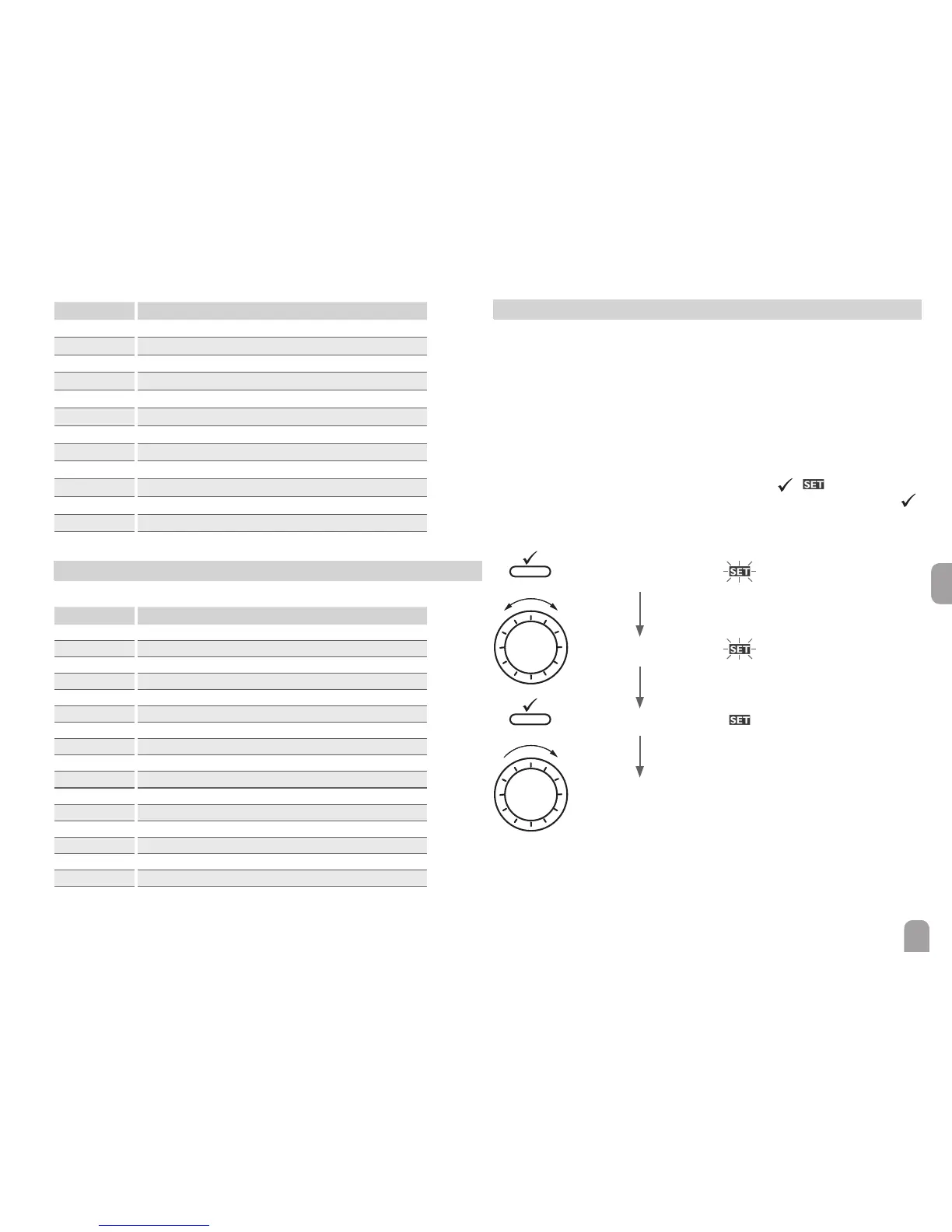
Commissioning menu
The commissioning menu consists of the channels described in the following. In
order to make an adjustment, press the right button (
). starts ashing and
the adjustment can be made. Conrm your selection with the right button (
).
Turn the Lightwheel
®
, the next channel will appear on the screen.
ashing
ashing
not ashing
adjustment mode
Operation
changing a value
conrming a value
to the next parameter

 Loading...