The unit must only be located internally. It is not suitable
for installation in hazardous locations and should not be
sited near to any electromagnetic field. The controller must
additionally be equipped with an all-polar gap of at least 3 mm
or with a gap according to the valid installaton regulations,
e.g. LS-switches or fuses. Please pay attention to a separate
laying of the cable lines and installation of ac power supply.
1. Unscrew the cross-recessed screw of the cover and
remove it from the housing.
2. Mark the upper fastening point on the underground and
premount the enclosed dowel and screw.
3. Hang up the housing at the upper fastening point and mark
the lower fastening point on the underground (hole pitch
130 mm), afterwards put the lower dowel.
4. Fasten the housing at the underground.
Warning!
Switch-off power supply before
opening the housing.
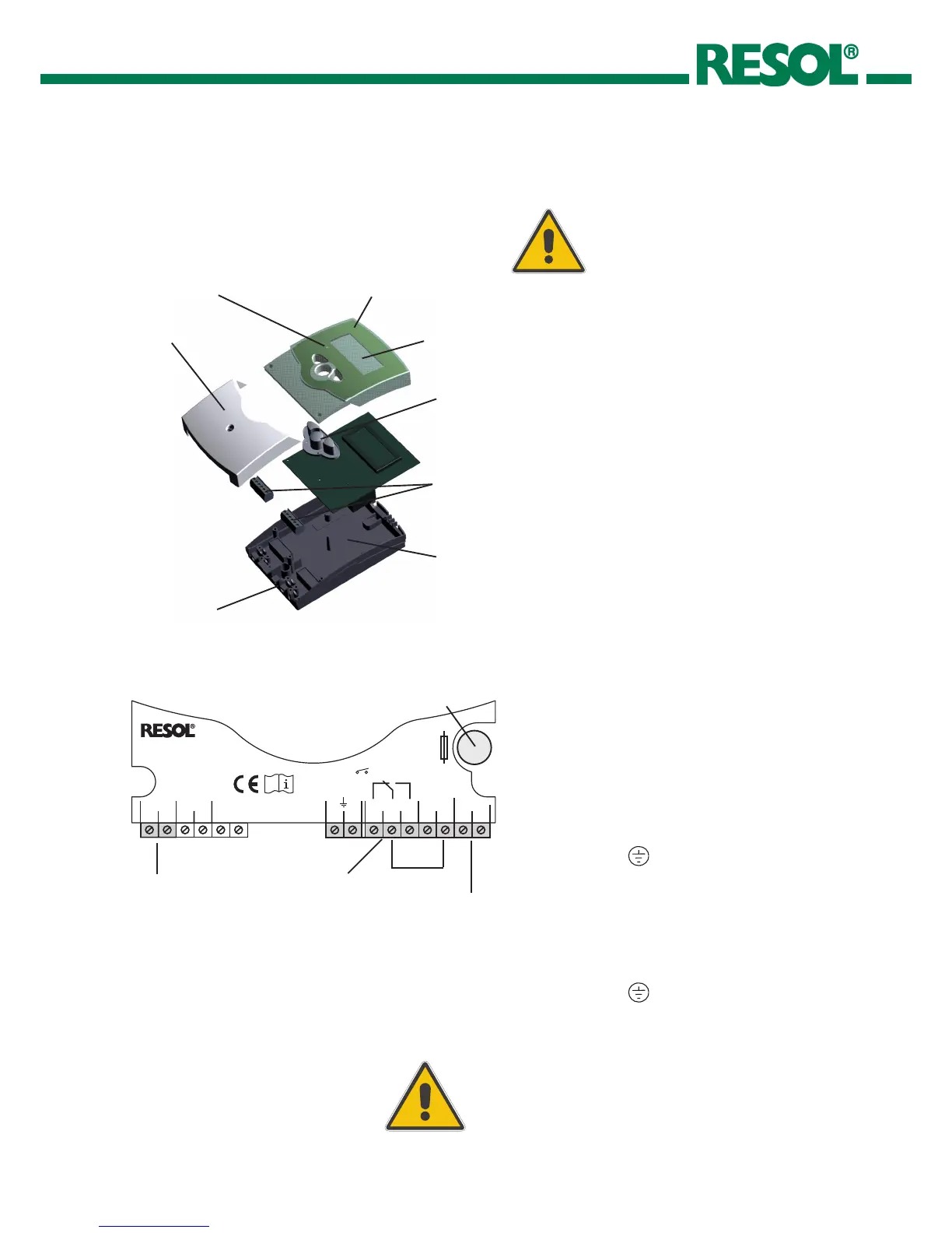
housing
key field
base
clamps
cover
cable conduits with strain relief
operation control lamp
combined LCD
2.1 Mounting
2. Installation
2.2 Electrical connection
The power supply to the controller must only be made by
an external power supply switch (last step of installation!)
and the line voltage must be 220 ... 240 Volt (50...60 Hz).
Flexible lines are to be fixed at the housing by enclosed
strain relief supports and screws.
The controller is equipped with 1 standard relays, to
which the consumers can be connected:
14 = normally closed contact R
15 = middle contact M
16 = normally open contact A
13 = ground clamp
The temperature sensors (S1) will be connected to the
following terminals independently of the polarity:
1 / 2 = sensor for heat source / heat sink
The power supply is effected to the clamps::
19 = neutral conductor N
20 = conductor L
12 = ground clamp
net clamps
sensor clamps
consumer clamps
Notice:
The middle contact M (15) and the conductor L (18) are
bridged from factory.
After removal of the bridge the changeover contact (RMA)
becomes a potential-free relais.
bond bridge