Table of Contents:
THE MERCURY & INTUITIVE RANGE .............................................................................................................. 4
Variants ............................................................................................................................................................ 4
Compatible Displays ........................................................................................................................................ 4
Configuration ..................................................................................................................................................... 4
Compatible Network Interfaces ........................................................................................................................ 4
Front Display Features ...................................................................................................................................... 5
Connections ....................................................................................................................................................... 5
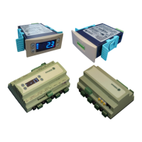
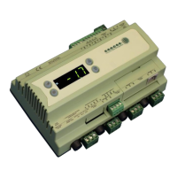
Mercury Mk2 6-5E and 6-5M ............................................................................................................................. 5
Intuitive Mercury Controller Intuitive Mercury Network Expansion Options ...................................... 6
Ordering Information ........................................................................................................................................ 6
Input and Output Allocation Tables ................................................................................................................. 7
Input / Output allocation table .......................................................................................................................... 7
Switched Resistor Values ................................................................................................................................ 7
Setting up the controller ................................................................................................................................... 7
Setup through front buttons ............................................................................................................................. 7
Setup Function Menu ....................................................................................................................................... 8
Recommended set-up method ......................................................................................................................... 8
rtc. Real time clock (This will automatically synchronise on network systems) ............................................... 8
type. Set/view controller type ........................................................................................................................... 8
PArA. Set/view parameters (This can be achieved at the network front end) ................................................. 8
Unit. Set/view temperature unit and Probe type .............................................................................................. 8
Display.............................................................................................................................................................. 9
Parameter Tables ............................................................................................................................................... 9
Parameter Descriptions .................................................................................................................................. 10
Relay State and functional operation ............................................................................................................ 12
Relay and screen states during defrost ........................................................................................................ 13
*The defrost relay will cycle around the termination setpoint during defrost min if defrost type is set to
elec/cln, otherwise it will be off. ...................................................................................................................... 13
Defrost Type (P-91) ........................................................................................................................................ 13
Defrost Termination ........................................................................................................................................ 13
Fan Delay after Defrost .................................................................................................................................. 13
Network Configuration .................................................................................................................................... 13
RS485 Legacy module / Intuitive Internal RS485 Network card .................................................................... 13
Wireless Mesh Communication Module ......................................................................................................... 14
Fast Network Address Reset ......................................................................................................................... 14
IP Futura module / Intuitive Internal IP Network card .................................................................................... 14
Mercury Switch ................................................................................................................................................ 15
Viewing ............................................................................................................................................................. 15
Input / Output Table ....................................................................................................................................... 15
Maximum and Minimum Control Temperature............................................................................................... 16
Messages .......................................................................................................................................................... 16
Network Alarms ............................................................................................................................................... 16
Modifying controller states ............................................................................................................................. 16
Fans Only “FAnS” .......................................................................................................................................... 17
Case Off “CASE” ............................................................................................................................................ 17
Lights Only “Ligt” ............................................................................................................................................ 17
Probe Offset ................................................................................................................................................... 17
Remote Commands ......................................................................................................................................... 17
Power requirements ....................................................................................................................................... 18
General........................................................................................................................................................... 18
Relay Specification ......................................................................................................................................... 18
Specification .................................................................................................................................................... 18
Inputs.............................................................................................................................................................. 19
Switched Resistor Example Wiring ............................................................................................................... 19
Installation ........................................................................................................................................................ 19
Dimensions ...................................................................................................................................................... 19