01
FUNCTIONS & FEATURES
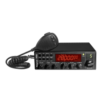
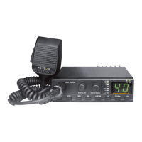
1. Large LCD panel which displays frequency and all kinds of information
2. DUAL-DIGITAL TUBE FOR CHANNEL DISPLAY
3. USE EL technology for backlight
4. PA、CW、AM、FM、USB、LSB mode
5. A、B、C、D、E、F , 6 banks in total, where 60 channels at least can be individually programmed.
6. Frequency Tuning Step can be 10HZ, 100HZ, 1KHZ or 10KHZ.
7. Multiple CLARIFIER Operating Modes
8. Flexible menu functions and PC programming software to meet varied customer demands
9. ECHO Function
10.SQ, ASQ Function (FM and AM mode only)
11.RF GAIN ADJUSTMENT
12.RF Power ADJUSTMENT
13.SCAN FUNCTION
14.RB FUNCTION
15.NB/ANL FUNCTION
16.DW DUAL-WATCH FUNCTION
17.BEEP VOICE PROMPT
18.+10KHZ Function
19.SWR、S/RF、DC Voltage display function
20.TOT function
21. HI-CUT FUNCTION
22.EMG CALL
23.SWR PROTECTION
24.POWER SUPPLIED VOLTAGE PROTECTION
25.Key-Lock Function
26.VOX function
27.CTCSS/DCS code
28.RX compander: noise blanker
29.Noise gate setting: mic noise adjustable
30.RX Noise Reduction
31.Compatible with “electronic” and “dynamic” MIC type
WARNING
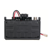
To use the radio, please connect the antenna to the jack "B" on the back panel of the equipment rst and then measure the SWR
(Standing Wave Ratio) before transmitting (at this subject read the chapter nr.5/ page 3). A badly tuned antenna can destroy the nal
TX amplier, these components are NOT covered under warranty.
INSTALLATION
1. WHERE AND HOW TO MOUNT YOUR RADIO
a) It is impoant to identify the proper place of the installation by considering "key criteria", such as easy access and congenial spaces
with freedom of movement.
b) The radio must not compromise the comfo of either: the driver and the passengers.
c) Remember to provide cables in harmony with safety and prevention "standards". As well as guide their wiring in protected channels
(eg: power supply, antenna, accesso wiring), so that they do not inteere in any way with the driving of vehicles.
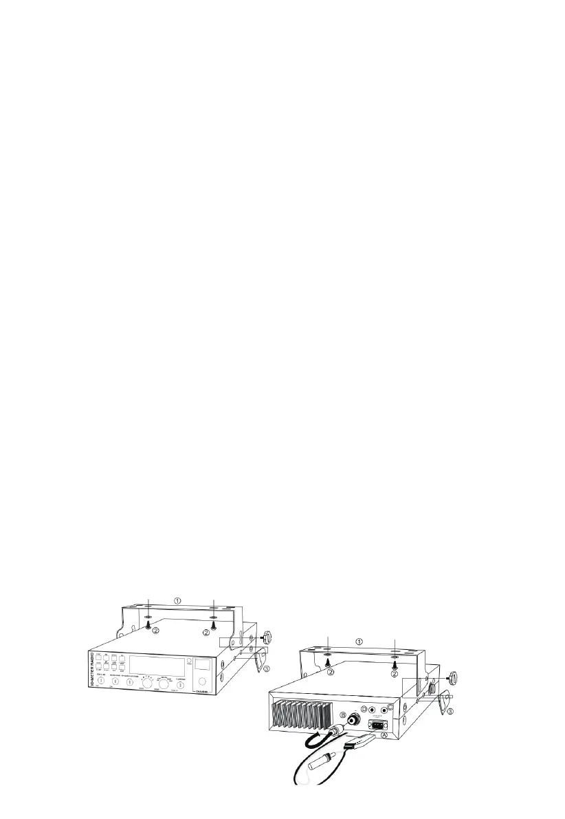
d) To install your equipment, use the bracket (1) and the self-tapping screws [2] provided (drilling diameter 5 mm). Be careful not to
damage the vehicle's electrical system when drilling the dashboard.
e) Do not forget to inse the rubber joints [3] between the radio and its bracket as they have a cushioning eect that allows a delicate
orientation and tightening of the device.
f) Choose where to place the microphone holder and remember that the microphone cable must extend to the driver without
inteering with the vehicle's controls.
2. ANTENNA INSTALLATION