03
5. ADJUSTMENT OF SWR (standing wave ratio)
WARNING: This process must be carried out when you use your radio for the rst time (and whenever you re-position your antenna).
The adjustment must be carried out in an obstacle-free area.
Adjustment with a built-in SWR meter or external SWR meter
a) To connect the SWR meter Connect the SWR meter between the radio and the antenna as close as possible to the radio (use a
maximum of 40cm cable).
b) To adjust the SWR meter
-Set the radio to channel 20 at the D bank in FM.
-Slide the switch on the SWR meter to position CAL or FWD.
-Press the <<Push-To-Talk>> switch on the microphone to transmit.
-Adjust the index needle over ▼ sign by rotating the calibration knob.
-Change the switch to position SWR (reading of the SWR level). The reading on the meter should be as near as possible to 1. If this is
not the case, re-adjust your antenna to obtain a reading as close as possible to 1. ( An SWR reading between 1 and 1.8 is acceptable).
-It will be necessa to re-calibrate the SWR meter after each adjustment of the antenna.
6. HOW TO USE AN EXTERNAL SWR METER
-Set to channel 20 on D bank in FM.
-Press the <<push-to-talk>> button on the microphone to transmit.
-At the moment, LCD would display SWR value which should be as close as possible to 1. If this is not the case, re-adjust your antenna
to obtain a SWR value as close as possible to 1 (an SWR reading between 1 and 1.8 is acceptable).
HOW TO USE YOUR RADIO
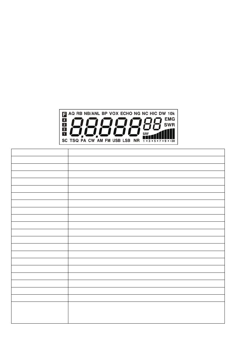
<LCD Display>
7 digits
Indicating bars
The rst decimal point
F
AQ
RB
NB/ANL
BP
ECHO
VOX
NG
NC
HI-CUT
DW
10K
EMG
SWR
SRF
SC
TSQ
NR
PA、CW、AM、FM、USB、LSB
Display frequency and any other information.
Indicate RX, RSSI, PA, PWR, SWR.
Appears when the current channel is edited with SCAN DEL.
Appears after pressing the FUNC key.
Appears when the ASQ function is staed (only for AM/FM).
Appears when the Roger beep function is staed (enabled).
Appears when the NB/ANL function is staed (enabled).
Appears when the BP function is staed (enabled).
Appears when the ECHO function is staed (enabled).
Appears when the VOX function is staed.
Appears when the TX noise gate is staed.
Appears when the RX noise compander is staed.
Appears when the HI-CUT function is staed.
Appears when the DW function is staed.
Appears when the +10KHZ function is staed.
Appears when the EMG channel is used.
Appears when the SWR is used.
Appears when the S/RF is used.
Appears when the SCAN is used.
Appears when the CTCSS/DCS code is used.
Appears when the RX noise reduction is turned on.
Indicate dierent operating modes.
1. Appears when the CLARIFIER function is FINE operation.
2. Appears when the CLARIFIER FUNCTION is a COARSE operation or RT operation.
3. Appears when the CLARIFIER FUNCTION is transmitting frequency regulated.