Air Flow Balancing (cont’d)
DUCT DIAM.
5"
6"
CROSS SECTION AREA
0.136 sq. ft.
0.196 sq. ft.
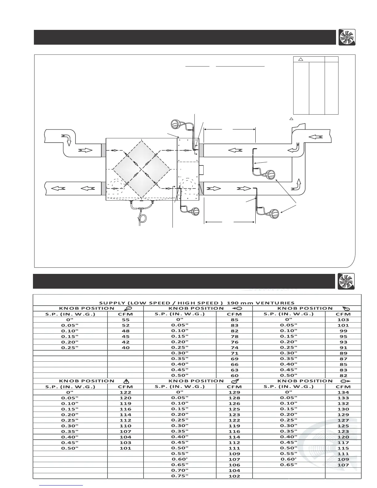
The accuracy of the flow reading will be affected by how close to any elbows or bends the readings are taken.
Accuracy can be increased by taking an average of multiple readings as outlined in the literature with the Pitot tube.
MAGNEHELIC
0
.1
.2
.3
.4
.5
MAGNEHELIC
0
.
1
.2
.3
.4
.5
Magnehelic
gauge
Pitot
tube
Pitot tube
Min 3 ft straight duct
(option #1)
Min 3 ft straight duct
MAGNEHELIC
0
.
1
.2
.3
.4
.5
(option #2)
(option #2)
Note: To take more accurate readings, use option #1(if possible).
Project and Project Condo Units use Option #1
Note:(Option #2)- Only for “superior” series
*For balancing, extension box cover plate is
provided with 3 holes on supply side and 3
holes on exhaust side.
*Do not use pitot tube to open holes in the
insulation as it may block/damage the pitot tube.
*Take 3 readings on each hole and average
all 9 readings for supply and same for exhaust.
*After finish balancing, plug all six holes with
plastic plugs provided with the unit.
Extension box cover plate
CFM = Opening / Cross-sectional Area(sq.ft.) x velocity(FPM)
Opening area: 0.2196sq.ft.
MAGNEHELIC
0
.1
.2
.3
.4
.5
Opening area: 0.136 sq.ft.
11
Ø5 Ø6
0.010 0.004 50
0.012 0.006 60
0.016 0.008 70
0.022 0.010 80
0.027 0.013 90
0.034 0.016 100
0.041 0.020 110
0.048 0.023 120
0.057 0.027 130
P"
CFM
P" = Velocity Pressure in inch
RERV - S100 AND RHRV - S100A/S100P
NOTES:-
Air Flow (CFM) Chart for Different Knob Position