Low Voltage
+5
DAT
C
Speed
Contact
L0/HI
Speed
HV Input
Remote
0n/0ff
HV
NC
C
N0
Ext. Interlock
HIGH VOLTAGE
Low Voltage
+5
DAT
C
Speed
Contact
L0/HI
Speed
HV Input
Remote
0n/0ff
HV
NC
C
N0
Ext. Interlock
HIGH VOLTAGE
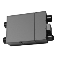
On some older thermostats, energizing the R and G terminals at the furnace has the effect of energizing Y at the
thermostat and thereby turning on the cooling system. If you identify this type of thermostat, you must use the
“Alternate Interlock Wiring”.
For a furnace connected to a cooling system:
Wiring Diagram (cont’d)
6
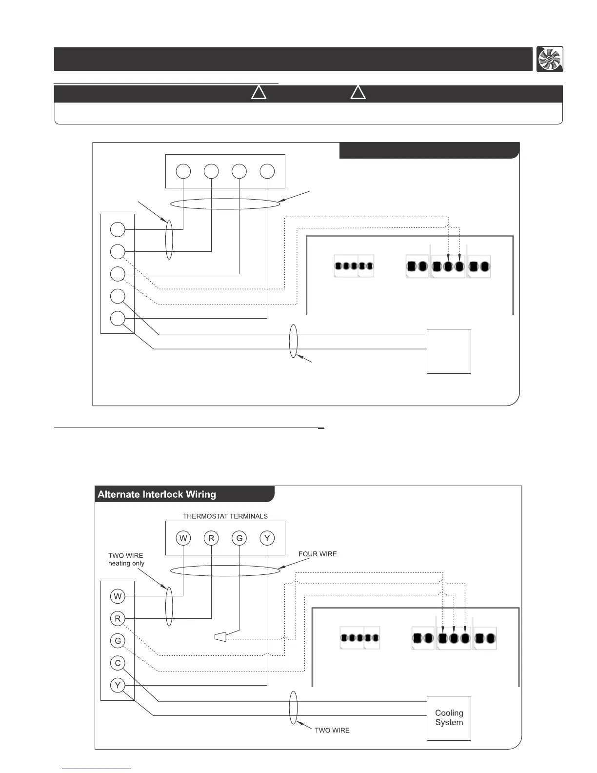
Furnace / Fan-Coil / Heat Pump Interlock:
Standard Interlock Wiring
W R G Y
W
R
G
Y
C
FOUR WIRE
TWO WIRE
heating only
Cooling
System
THERMOSTAT TERMINALS
TWO WIRE
Never connect a 120 volt AC circuit to the terminals of the furnace/fan-coil/heat pump interlock (Standard Wiring).
Only use the low voltage class 2 circuit.
W A R N I N G
! !