PUSH FOR FAN
M
I N
U T E
S
LO
HI
INT
g)
g) Intermittent Switch
(IC 100-5V)
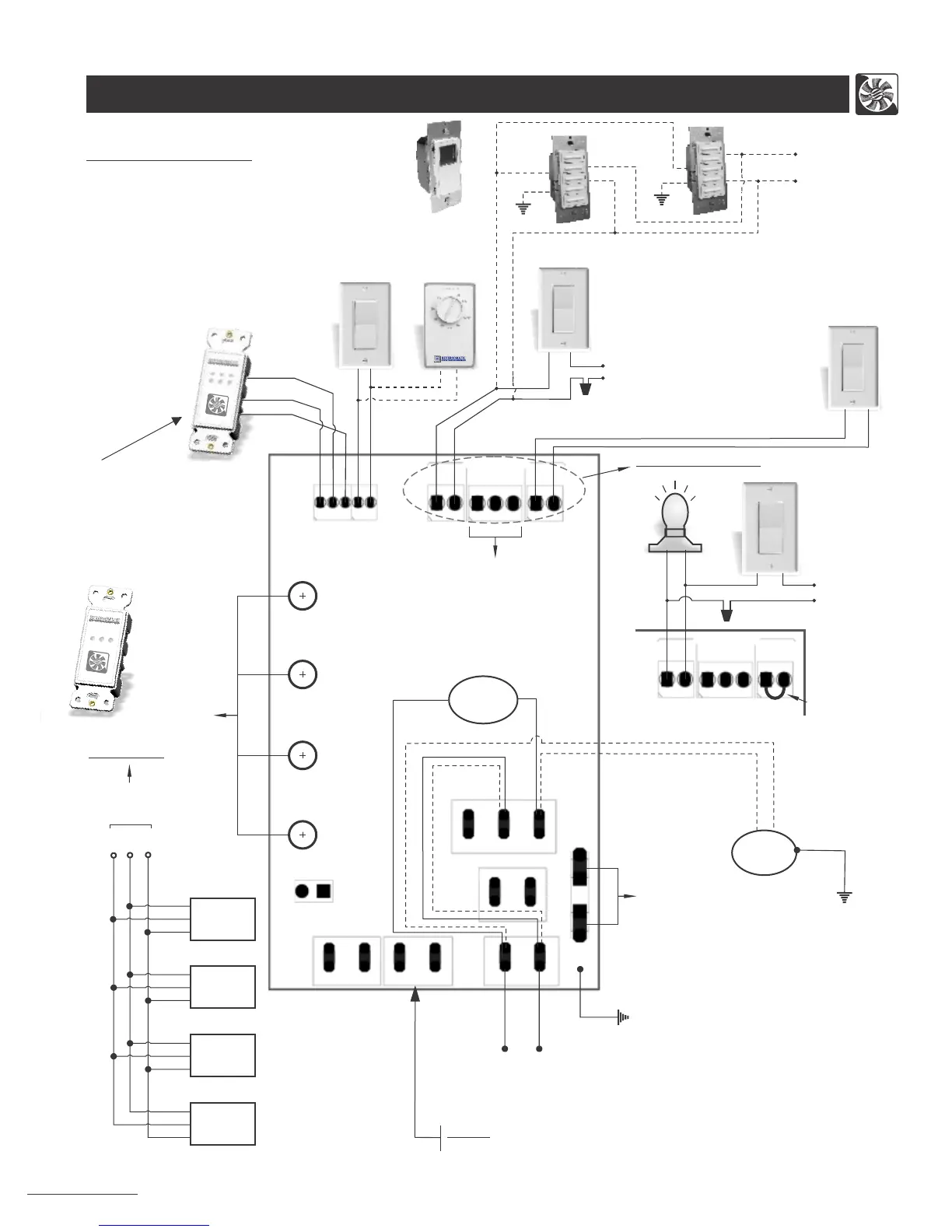
Wiring Diagram (Superior, Project, Economy and Maxum Series Unit)
5
CONTROL BOARD:
a) Timer Switch (TC100)
b) Wall Switch
c) Dehumidistat
d) Time Delay Switch (TC100-120 & TC100-120P)
e) Master On/Off Switch
for HRV/ERV
f ) Light
Optional Accessories (Not Supplied)
FAN2
FAN1
LINE
NEUTRAL
PUSH FOR F
AN
M
I
N
U
T
E
S
or
a)
b) c)
d)
Hi
Low
Light / Switch Option
120 Vac / 1 / 60Hz
Power Supply
Hi
Low
Furnace, Fan Coil,
Heat Pump
Interlock
4 - Speed Controller for Manual Balancing
and Air Flow Adjustment
120 VAC / 1 / 60Hz
Power Supply
Ground
Fuse
On
Off
e)
Low HighLow High
Exhaust
Fan Speed
Supply
Fan Speed
Supply Fan
Exhaust Fan
b)
Temp. Sensor
Safety Switch
Low Voltage
+5
DAT
C
Speed
Contact
L0/HI
SPEED
HV INPUT
Remote
0n/0ff
(HV-High Voltage)
NC
C
N0
Ext. Interlock
HIGH VOLTAGE
Damper Interlock
NC
C0M
N0
f)
HRV/ ERV
Hi / Low
Light
On / Off
120 Vac / 1 / 60Hz
Power Supply
Jumper
(remove jumper to install
master ON/OFF switch)
b)
L0/HI
Speed
HV Input
Remote
0n/0ff
HV
NC
C
N0
Ext. Interlock
HIGH VOLTAGE
FAN #1 - Single speed
(Bathroom Exhaust fan connection for “Project Series”)
Note:
Up to 4 Timer Switches (TC 100-5V)
can be
connected to control board of
HRV/ERV by using three 24 AWG (min.)
Copper wires as shown.
Maximum total wire length 75ft.
(see option 2)
Option 2:
Timer
Switch
2
Timer
Switch
3
Timer
Switch
4
to Control
Board
Note:
Make sure, the Line must be connected to
Line and Neutral connected to Neutral.
Unit will not function if not connected correctly.
RED
YEL
GND
RED
YEL
GND
C
+5
DAT
RED
YEL
GND
RED
YEL
GND
Model # RHRV-P100A
RHRV-P100P
RERV-P100
Note: Same power source must be
used if wall switches (b) & time delay switches (d)
are connected together in parallel.
TC100-120P
TC100-120
RED
BLACK
WHITE
Ground
120 Vac / 1 / 60Hz
Power Supply
(TC100-5V)
Important Note:- When installing timers or time delay switches, make sure
that they are for appropriate HRV/ERV models.
Ground
BLACK
WHITE
RED
Damper Motor
(Single Winding)
External Damper
Motor
Ground
Intermittent
OR Timer
RED
YEL
GND
Option-1
(Also available w/o OFF
mode)
Switch 1
and one intermittent switch (IC 100-5V)