r^;-:;:^,-
n^ox
B225
SECTION 3/4
3.2.2 Drawer motor control
The drawer motor amplifier (IClOa, R52,53,56,
57,
and
R58,
C14, Q8 and Q9) is controlled through the shift
register IC3 (pins 4 and 5). If the drawer movement
is blocked during the opening or closing operation,
the motor current rises and hence the voltage across
R64.
Signal Tl of the master processor consequently
changes'to "L" (circuit R40,54,55,59,63,
Q6,^Q7,
C13,
and
IClOb).
In response the master processor reverses
the direction of the drawer movement.
3.3
SERVO-2 PCB
1.769.330
The SERVO 2 PCB
1.769.330
contains the circuits for
radial control and the IR receiver.
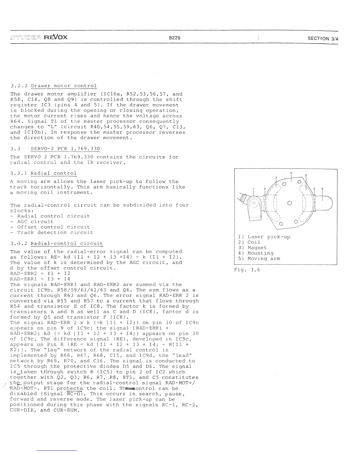
3.3.1 Radial control
A moving arm allows the laser pick-up to follow the
track horizontally. This arm basically functions like
a moving coil instrument.
The radial-control circuit can be subdivided into four
blocks:
- Radial control circuit
- AGC circuit
- Offset control circuit
- Track detection circuit
3.-3.2
Radial-control circuit
The value of the radial-error signal can be computed
as follows^ RE= kd (II +12+13 +14) - k (II + 12).
The value of k is determined by the AGC circuit, and
d by the offset control circuit.
RAD-ERR2 =11+12
RAD-ERR1 =13+14
The signals RAD-ERR1 and RAD-ERR2 are summed via the
circuit IC9b, R58/59/61/62/63 and Q6. The sum flows as a
current through R63 and Q6. The error signal RAD-ERR 2 is
converted via R55 and R57 to a current that flows through
R54 and transistor E of IC8. The factor k is formed by
transistors A and B as well as C and D
(IC8),
factor d is
formed by Q5 and transistor F
(IC8).
The signal RAD-ERR 2 x k (=k [II + 12]) on pin 10 of IC9c
appears on pin 9 of IC9c; the signal [RAD-ERR1 +
RAD-ERR2J kd (= kd [11 + 12 + 13 + 14j) appears on pin 10
of IC9c. The difference signal (RE), developed in IC9c,
appears on Pin 8 (RE = kd [II + 12 + 13 + 14
j
- K[I1 +
K2j ). The "lag" network of the radial control is
implemented by R66, R67, R68, C15, and IC9d, the "lead"
network by R69, R7
0,
and C16. The signal is conducted to
IC5 through the protective diodes D5 and D6. The signal
is^taken through switch B (IC5) to pin 2 of IC2 which
together with Q2, Q3; R6, R7", R8, RT1, and C5 constitutes
the_output stage for the radial-control signal RAD-MOT+/
-RAD-MOT-.
RT1 protects the
coil;-
ThJBMwontrol can be
disabled (Signal
RC-o).
This occurs in search, pause,
forward and reverse mode. The laser pick-up can be
positioned during this phase with the signals RC-1, RC-2,
CUR-DIR, and CUR-SUM.
 Loading...