c^.
=
KEI/OX
B225
SECTION 4/9
4
m
2 Adjustments on CD player B225
Note:
Cleanliness
in
the work area
is of
outmost importance
and ensures that
no
contaminants
or
metal particles
can enter into the
CD
mechanism.
If any work
on
printed circuit boards
is
necessary,
it
is
essential
to
observe the ESE recommendations
(refer
to
last page
of
contents).
Before putting the
CD
player into operation ensure
that the transport screws have been unfastened.
The
CD
player mechanism
is
equipped with self-lubricating
bearings which should not
be
lubricated.
If the drawer must
be
open and
a
disc mounted
in
order
to perform certain measurements
or
adjustments,
the
•rear light barrier must
be
interrupted (the detector
responds
as if
the drawer were closed) and the compact
disc must
be
secured with
a
removed adhesive magnet.
The optical system
of
the laser can
be
cleaned with
an air brush.
Coil Ll on the decoder PCB
1.769.300
is automatically
aligned by IC13 (SAA7010) and consequently requires
no adjustment*
4.2.1 Aids
-
DC
voltmeter
- Cathode ray oscilloscope
- Reference CD, frequency response, part No. 46240
- Reference CD, drop
outs,
part No. 46241
- Mirror
CD
for adjusting the optical system, part
No.
46242
- Set
of
service PCBs and cables, part No. 46230
- ESE work location kit, part No. 46200
4.2.2 Aligning
player mechanism, general
- Remove top cover.
- Connect
CD
player
to AC
supply and open the drawer
by pressing the LOAD key.
- Cover rear light barrier.
- Mount reference disc
5
(part No. 46241) and secure
it with
a
removed adhesive magnet.
- Selection
1 of
the
CD is to be
played for all alignment
work.
It
is, therefore^ advantageous
to
enter
the
LOOP.-command
in
programming mode.
"4T2".
3
Adjusting the laser current
- Switch
CD
player off, remove SERVO
2
PCB
1.769.330
and reinsert
it
via the service PCB (part No.
46230).
- Connect
DC
voltmeter
to
R63
on
SERVO
2
PCB.
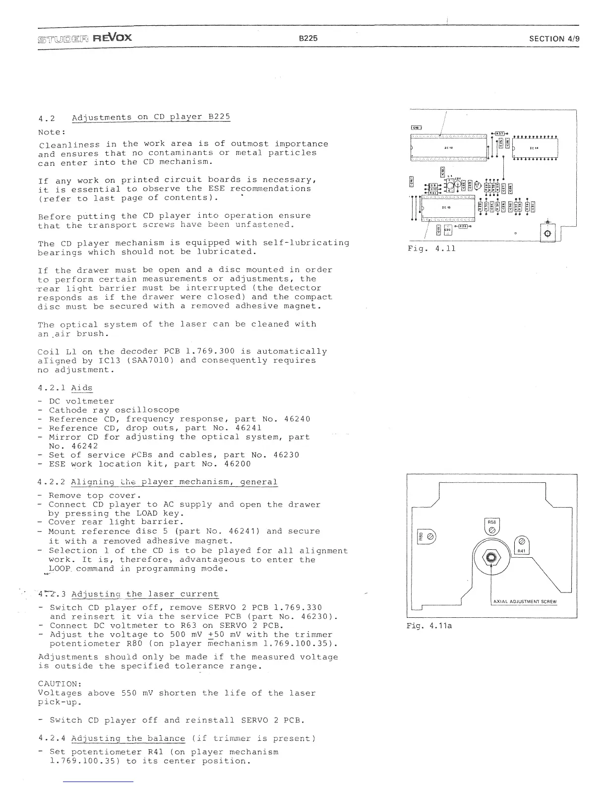
- Adjust the voltage
to
500
mV
+50
mV
with the trimmer
potentiometer RS0 (on player mechanism 1.769.100.35).
Adjustments should only
be
made
if
the measured voltage
is outside the specified tolerance range.
CAUTION:
Voltages above 550
mV
shorten the life
of
the laser
pick-up.
- Switch
CD
player off and reinstall SERVO
2
PCB.
4.2.4 Adjusting the balance (if trimmer
is
present)
- Set potentiometer R41 (on player mechanism
1.769.100.35)
to
its center position.
 Loading...