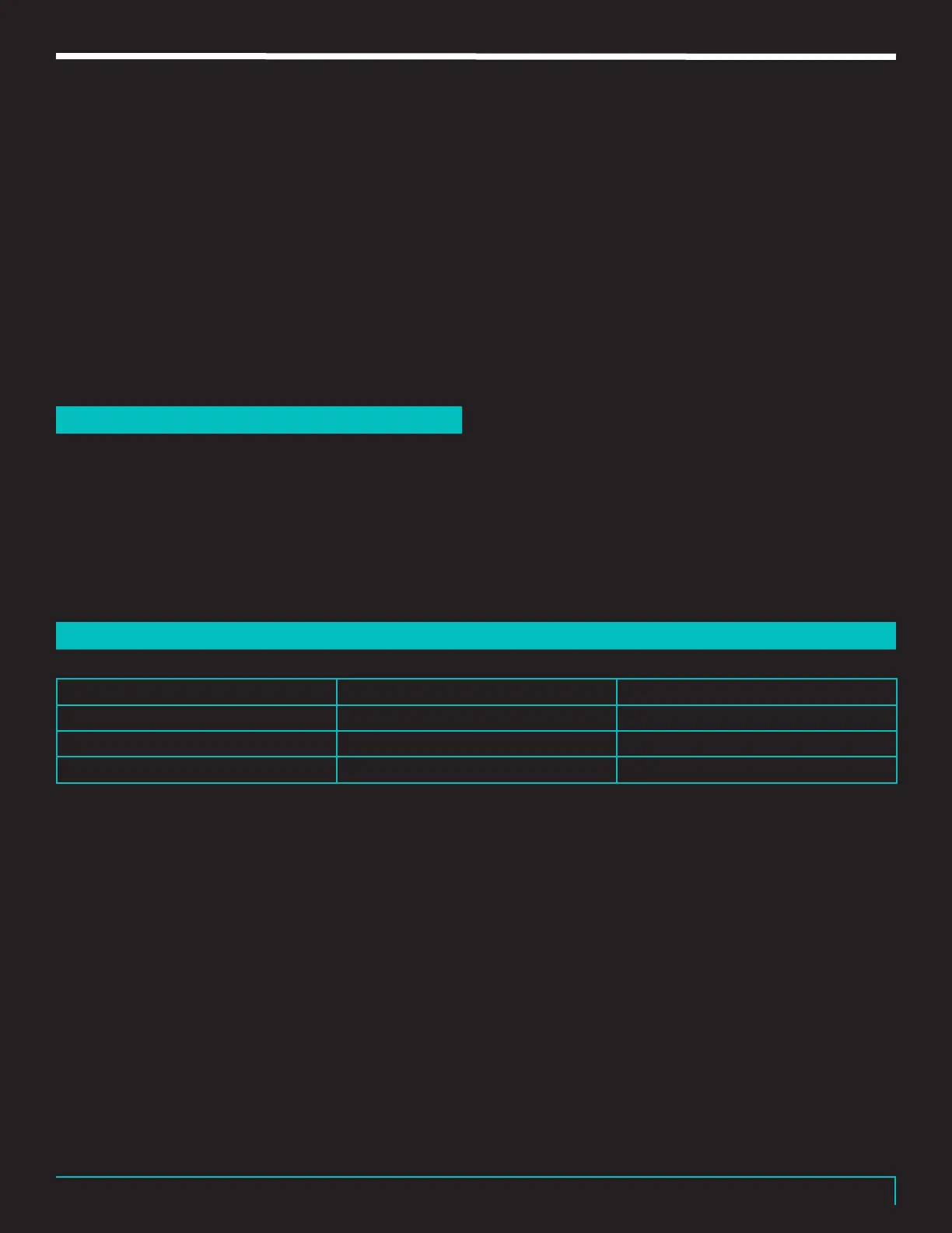
REVV | GENERATOR 100P MK3
15
3. Now plug the amplifier into the main power
receptacle, unplug any guitar cables from the
inputs & turn on the main power. Let the tubes
warm up for one minute
4. Turn down the master volume controls to zero &
turn on standby to the ON position.
5. Verify that none of the tube fault LEDs are on. If
they are, power down the amplifier, remove the
plug from the main power receptacle & replace the
faulty fuse & return to step 3. If everything checks
out, move on to the next steps of setting the bias.
If it is still blowing fuses, a tube is at fault. Try a
dierent pair.
SETTING THE BIAS
35
1. Place the black lead from your meter into the black bias
test point on the amplifier & the red lead into the red
bias test point (The red test point on the left is for V1 & V3
tubes, red test point on the right is for V2 & V4 tubes).
2. Refer to the chart below for bias set points for the
tubes being used & slowly turn the trimmer in the
clockwise direction until the value is reached.
3. Next, place the red lead into the other red bias test
point & repeat step 2 for the other set of tubes. If 2
dierent pairs of tubes are being used, refer to the
chart below & set the bias accordingly.
4. Re-check the settings of each bias test point &
make any further adjustments as required.
5. Once the bias is set at the required settings, return
the chassis into the headshell if removed and rear
bae panel to the rear of the amp & fasten it with
the screws you removed. You are done!
(Measurements are for two tubes per bias point)
Note: The range setting is for experimentation. Power
tube bias settings change the sound of the amp & the
range listed above is safe for experi-mentation. The
largest setting is considered the maximum setting &
should not be set above this setting. Running the tubes
on the higher end of the range will shorten the tubes
expected life.
BIAS CHART
36
Type Recommended set point Safe Range
KT88 100mV 90mV to 110mV
EL34 70mV 60mV to 80mV
6L6GC 85mV 80mV to 95mV