Form I-ADF, P/N 131805 R6, Page 13
FIGURE 9A - Optional
Screened Outside Air
Hood with Filters
Factory assembled and
shipped separately for eld
installation.
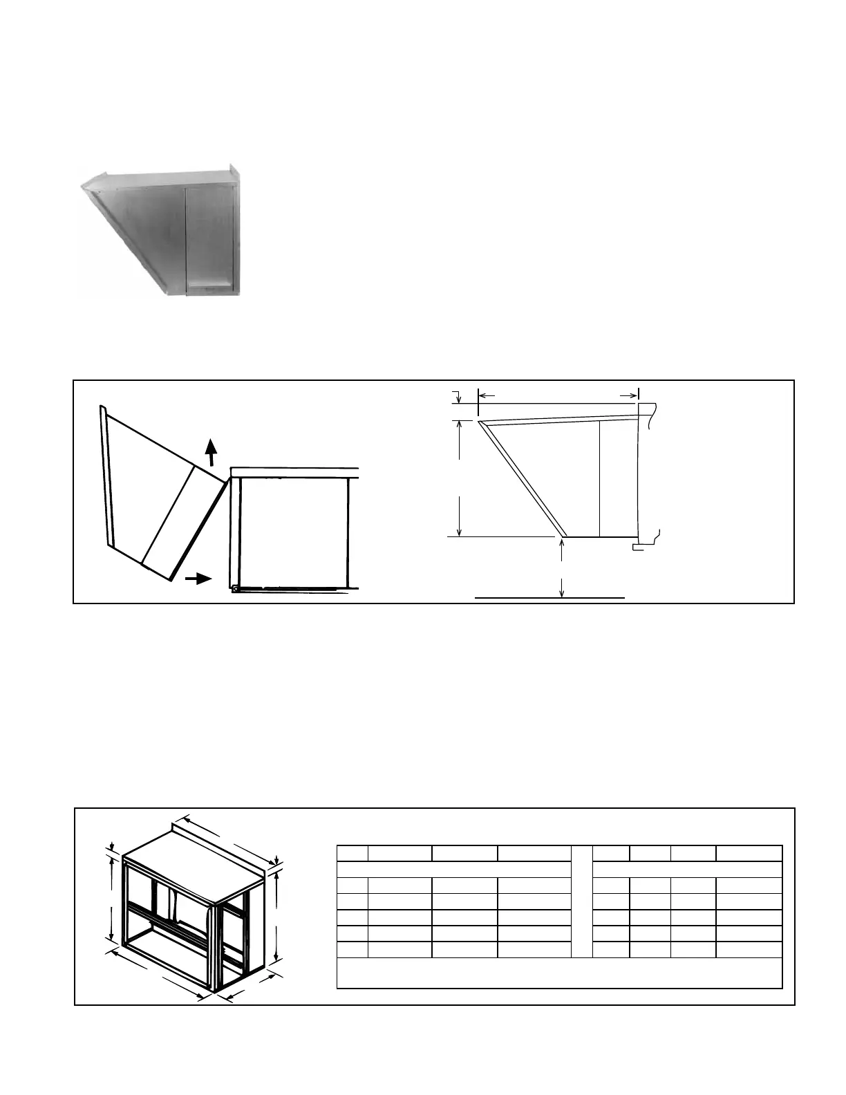
FIGURE 9B -
Installation and
Dimensions of Outside
Air Hood with Filters
Instructions for installing pre-assembled outside air hood with lters:
1. On the inlet air end of the system, remove the row of factory-installed screws
attaching the cabinet top.
2. Tip the assembled air hood slightly and slide the top ange underneath the cabinet
top. The air hood must be between the cabinet top and the end panel. Slide the
side anges into the slots between the corner posts and the end panel. (See
FIGURE 9A).
3. Re-insert all of the screws across the top of the cabinet.
4. The air hood bottom should be resting on the factory-installed support angle across
the bottom of the cabinet. If the bottom panel does not rest tightly against the
support angle, follow these instructions to adjust the position of the support angle:
a) Slightly loosen (do not remove) the support angle screws.
b) Slide the support angle up (holes are slotted) so that it is against the bottom
panel.
c) Tighten the screws.
5. If equipped with an optional dirty lter switch, locate the coil of clear tubing
attached to the dirty lter switch in the electrical compartment. Extend the tubing to
the air entering side of the lter rack. Attach the end of the tubing being careful that
it is not compressed or kinked. (See Paragraph 7.3 for switch details.)
Slide the air hood top ange
underneath the cabinet top.
NOTE: Width is
the same as cabi-
net without lters;
see FIGURE 8A.
The optional lter cabinets are designed for eld attachment to systems that are
installed indoors. The cabinet has a 1" duct ange for attachment of ductwork to bring
in outside makeup air to the system. The cabinet is available with 1" or 2" permanent,
2" disposable, or 2" pleated disposable lters. There is a lter access door on both
sides of the cabinet.
Installation Instructions: The cabinet and lter racks with lters are factory assembled
and shipped separately for attachment to the system at the job site.
1. On the inlet end of the system, remove the row of factory-installed screws
attaching the cabinet top.
2. Tip the assembled lter cabinet slightly and slide the top ange underneath the
cabinet top. (Refer to FIGURE 9B above.)
6.2.3 Indoor Filter
Cabinet - Options
AW3, AW6, AW13,
AW15
FIGURE 10 - Dimensions of Indoor Filter Cabinet
Size 300 500 700/1200 Size 300 500 700/1200
Dimensions (inches) Dimensions (mm)
A 34-1/8 47-13/16 58-15/16 A 867 1214 1497
B 33-1/16 33-1/16 33-1/16 B 840 840 840
C* 16-13/16 16-13/16 16-13/16 C* 427 427 427
D** 31-1/4 45 56 D** 794 1143 1422
E** 30-1/2 30-1/2 30-1/2 E** 775 775 775
* Includes 1" duct ange extending perpendicular to the duct opening.
** Duct connection.
The lter cabinet ange must be between the cabinet top and the end panel. Slide
the side anges into the slots between the corner posts and the end panel.

 Loading...


