Form I-ADF, Page 16
Thread
bleed line
tting (hose
barb) into
the adapter;
attach a
1/4" hose.
FIGURE 15 - Bleed Line Fitting
Bleed Line Connection (Does not apply to module with optional timed
metering system.) - Shipped in the evaporative cooling module bottom
pan, nd a 1/4" I.D. x 1/2" N.P.T. nylon bleed line tting (hose barb). Thread
the tting into the female adapter located opposite the pump/inlet side of
the water distribution line. The hose barb will protrude from the side of the
cabinet (FIGURE 15). Attach a 1/4" I.D. hose to the barb and run the hose to
the nearest drain.
Discharging a quantity of water by "bleed off" will limit the concentration of
undesirable minerals in the water being circulated through the cooling module.
Minerals buildup because evaporation only releases "pure water vapor" causing
the concentration of contaminants in the water to increase as the evaporation
process continues to occur. The minerals accumulate on the media, in the
water lines, on the pump, and in the reservoir. Adequate bleed off is important to
maintaining an efciently operating evaporative cooling system.
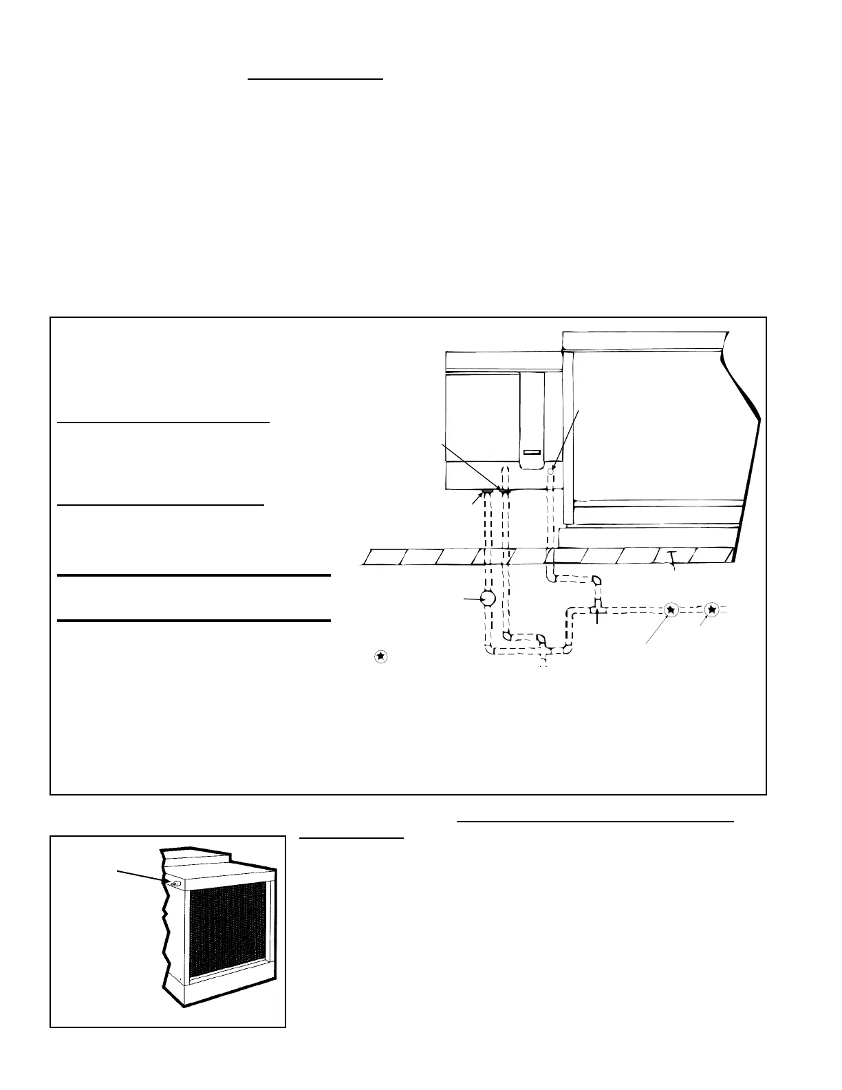
Supply and Drain Water Connections (cont'd)
FIGURE 14 - Water
Connections including
Optional Drain and Fill
Kit
Instructions for Installing Optional Fill & Drain Kit
NOTE: Follow this part of the instructions included in the valve pack-
ages for attaching valves to the water line only. The remainder of the
instructions with the valves do not apply to this type of application.
Water Line Connections (See illustration)
Supply (3-Way Valve) Connections - connect
the water supply line to "B" (normally closed).
Connect the water drain line to "A" (normally
open). Connect the middle outlet to supply
the water to the cooling module reservoir.
Drain (2-Way Valve) Connections - Connect
the drain pipe from the reservoir to "A".
Connect the outlet side to "B" and connect
into drain lines from the cooling reservoir and
the supply valve.
WARNING: Risk of electrical
shock. Disconnect the power.
Electrical Connection (requires black and
white 14-gauge wires) - Refer to furnace
wiring diagram:
1. Refer to the wiring diagram for terminal connections (NOTE: If kit is not ordered with the system, connections will not be
shown on the diagram. Terminal connections are specic to each system. Contact the factory for terminal connections. Be
prepared to provide all model information.)
2. Run eld-supplied black wire from the electrical compartment (terminal on the wiring diagram) of the evaporative cooling
module and connect to the black wire on both the 3-way and the 2-way valve.
3. Run eld-supplied white wire from the electrical compartment (terminal on the wiring diagram) of the evaporative cooling
module and connect to the white wire on both the 3-way and the 2-way valve.
6.0 Mechanical
(cont'd)
6.2 Unit Inlet Air
(cont'd)
6.2.4 Evaporative
Cooling Module -
Options AS4 and AS8
(cont'd)
All Cooling Modules - A manual water shutoff should be installed upstream of the
inlet, at a convenient non-freezing location, to allow the water supply to be turned on
and off. If necessary, install a bleed line between the manual valve and the cooling
module inlet to allow drainage of the line between the shutoff valve and the cooling
module.
All cooling modules are equipped with an overow and drain tting. The ttings are
in the cabinet bottom and come complete with a locknut and a sealing gasket. Check
these ttings for tightness before installing the overow and drain piping. The drain and
overow tting will accommodate a 3/4" garden hose thread and is tapped with a 1/2"
female pipe thread for iron pipe.
An optional automatic ll and drain kit (Option CT1) is available that will automatically
release supply water to the cooling module when a call for cooling is made and will
drain all water from the reservoir when the cooling switch is deactivated or a cooling
thermostat is satised. See FIGURE 14. If installing an optional ll and drain kit, follow
the instructions. Consult the wiring diagram for electrical connections.

 Loading...


