7
UBX-UBZ-UDX-UDZ-IOM (07-23) 1034344-K
Mounting Height Requirements
⚠ WARNING ⚠
If touched, the vent pipe and internal heater surfaces that are accessible from outside the heater
will cause burns. Suspend the heater a minimum of 5 feet (1.5 meters) above the floor.
In general, a unit should be located 8 to 12 feet (2.4 to 3.7 meters) above the floor. At those points where infiltration
of cold air is excessive, such as at entrance doors and shipping doors, it is desirable to locate the unit so that it will
discharge directly toward the source of cold air from a distance of 15 to 20 feet (4.6 to 6.1 meters).
Hazards of Chlorine
NOTE: Remember, chlorine is heavier than air. This fact should be kept in mind when determining
the installation location of heaters and building exhaust systems.
The presence of chlorine vapors in the combustion air of heating equipment presents a potential corrosion hazard.
Chlorine, found usually in the form of Freon or degreaser vapors, when exposed to flame will precipitate from the
compound and form a solution with any condensation present in the heat exchanger or associated parts. The result
is hydrochloric acid, which readily attacks all metals, including 300 grade stainless steel. Care should be taken to
separate these vapors from the combustion process. This may be done by wise location of the unit with regard to
exhausters or prevailing wind directions.
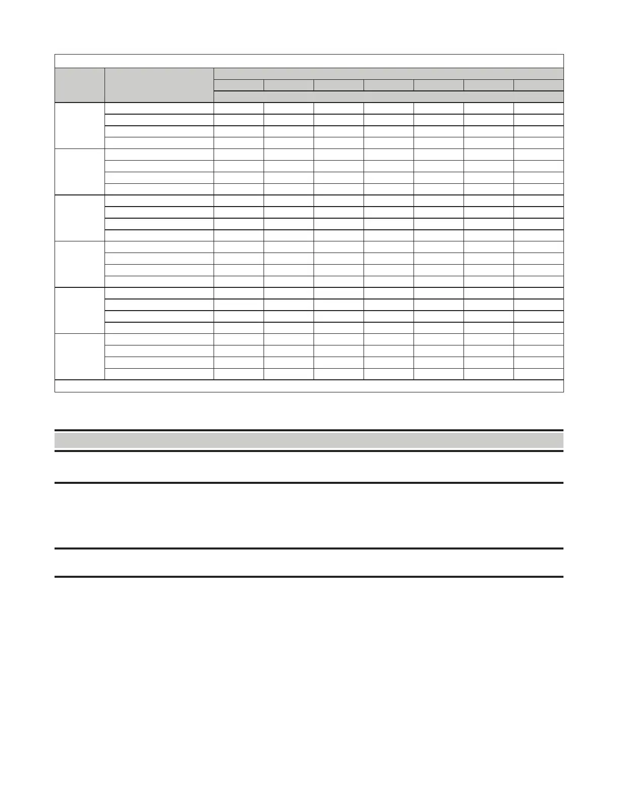
Table 3. Heater Throw Distances with Standard Horizontal Louvers
H*
(Feet
(Meters))
Distance* or Angle
Unit Size
175 200 225 250 300 350 400
Feet (Meters)
8 (2.4)
X 15 (4.6) 16 (4.9) 14 (4.3) 16 (4.9) 15 (4.6) 17 (5.2) 18 (5.5)
Y 28 (8.5) 30 (9.1) 27 (8.2) 29 (8.8) 28 (8.5) 31 (9.4) 34 (11.3)
Z 90 (27.4) 93 (28.0) 86 (26.2) 93 28.3 94 (28.7) 105 (32.0) 113 (34.4)
Downward louver angle 22° 20° 24° 21° 24° 20° 17°
10 (3.0)
X 17 (5.2) 17 (5.2) 15 (4.6) 17 (5.2) 16 (4.9) 18 (5.5) 20 (6.1)
Y 29 (8.8) 31 (9.4) 27 (8.2) 30 (9.1) 28 (8.5) 32 (9.8) 35 (10.7)
Z 87 (26.6) 91 (27.7) 82 (25.0) 90 27.4 89 (27.1) 103 (31.4) 110 (33.5)
Downward louver angle 27° 25° 30° 26° 29° 25° 21°
12 (3.7)
X 18 (5.5) 18 (5.5) 16 (4.9) 18 (5.5) 17 (5.2) 19 (5.8) 21 (6.4)
Y 29 (8.8) 31 (9.4) 27 (8.2) 30 (9.1) 28 (8.5) 32 (9.8) 36 (11.0)
Z 84 (25.6) 88 (26.8) 78 (23.8) 87 26.5 85 (25.9) 98 (29.9) 108 (32.9)
Downward louver angle 32° 30° 35° 31° 34° 30° 25°
14 (4.3)
X 18 (5.5) 19 (5.8) 16 (4.9) 18 (5.5) 17 (5.2) 20 (6.1) 23 (7.0)
Y 28 (8.5) 30 (9.1) 26 (7.9) 30 (9.1) 27 (8.2) 32 (9.8) 35 (10.7)
Z 79 (24.1) 84 (25.6) 73 (22.3) 83 25.3 80 (24.4) 95 (29.0) 105 (32.0)
Downward louver angle 37° 34° 41° 36° 40° 34° 29°
16 (4.9)
X 18 (5.5) 19 (5.8) 16 (4.9) 19 (5.8) 17 (5.2) 21 (6.4) 23 (7.0)
Y 27 (8.2) 29 (8.8) 24 (7.3) 28 (8.5) 25 (7.6) 31 (9.4) 35 (10.7)
Z 74 (22.6) 79 (24.1) 67 (20.4) 78 23.8 74 (22.6) 90 (27.4) 101 (30.8)
Downward louver angle 42° 39° 47° 41° 45° 38° 33°
18 (5.5)
X 17 (5.2) 19 (5.8) 14 (4.3) 18 (5.5) 16 (4.9) 20 (6.1) 23 (7.0)
Y 26 (7.9) 28 (8.5) 22 (6.7) 27 (8.2) 24 (7.3) 30 (9.1) 35 (10.7)
Z 68 (20.7) 74 (22.6) 60 (18.3) 72 (21.9) 66 (20.1) 85 (25.9) 97 (26.9)
Downward louver angle 48° 44° 53° 46° 51° 43° 37°
*See Figure 1.
—Continued
 Loading...