36
UBX-UBZ-UDX-UDZ-IOM (07-23) 1034344-K
MAINTENANCE—CONTINUED
Maintenance Procedures—Continued
Burner Orifice Maintenance
The burner orifice usually needs to be replaced only when installing a gas conversion kit. When ordering a replacement
orifice only, provide BTUh content and specific gravity of gas as well as the model and serial number of the unit.
When removing or replacing the burner orifice, take care not to damage the venturi tube and/or the bracket.
Heat Exchanger Maintenance
NOTE: Inspection of the lower portion of the heat exchanger is done with the burner removed.
Refer to the Burner Maintenance section for information on inspecting the lower portion of the
heat exchanger.
1. Remove burner in accordance with Burner Maintenance section.
2. Remove any external dirt or dust accumulation.
3. Visually inspect heat exchanger for cracks and holes.
4. If crack or hole is found, replace heat exchanger.
5. Install burner in accordance with Burner Maintenance section.
Ignition System Maintenance
• The DSI control module (circuit board, see Figure 10) monitors the operation of the heater including ignition. The
only replaceable component is the 3-amp Type ATC or ATO fuse (color code: violet, PN 201685). If the fuse is
blown, the problem is most likely an external overload. Correct the problem and replace the fuse.
• Do not attempt to disassemble the control module. However, check the lead wires each heating season for insulation
deterioration and good connections.
• For the flame sensor (see Figure 11 for location), disconnect the wire and remove the screw and the flame sensor.
Clean flame sensor with an emery cloth before reinstalling.
• Proper operation of the direct spark ignition system requires a minimum flame signal of 1.0 microamps as measured
by a microampmeter.
⚠ CAUTION ⚠
When reassembling, the brown ground wire must remain attached to the ignitor.
• For the ignitor (see Figure 11 for location), disconnect the wire and remove the screw and ignitor. Clean the ignitor
assembly with an emery cloth before reinstalling.
⚠ WARNING ⚠
Due to high voltage on the spark wire and electrode, do not touch when energized.
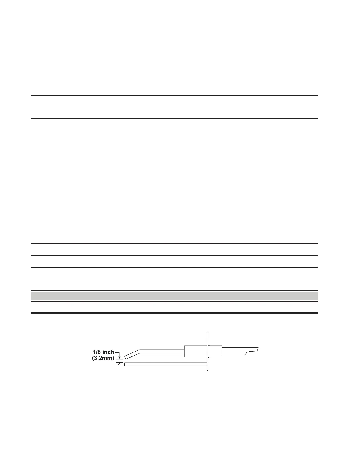
• The spark gap (see Figure 16) must be maintained to 1/8 inch.
Figure 16. Ignitor Spark Gap
Maintenance of Fan Motor, Fan Blades, and Fan Guard
Inspect and clean the motor, fan guard, and blades. Remove any dirt and grease. Take care when cleaning the fan
blades so as prevent causing misalignment or imbalance. Check to ensure that the hub of the fan blades is secure
to the shaft. If necessary, replace the assembly as follows:

 Loading...


