17
UBX-UBZ-UDX-UDZ-IOM (07-23) 1034344-K
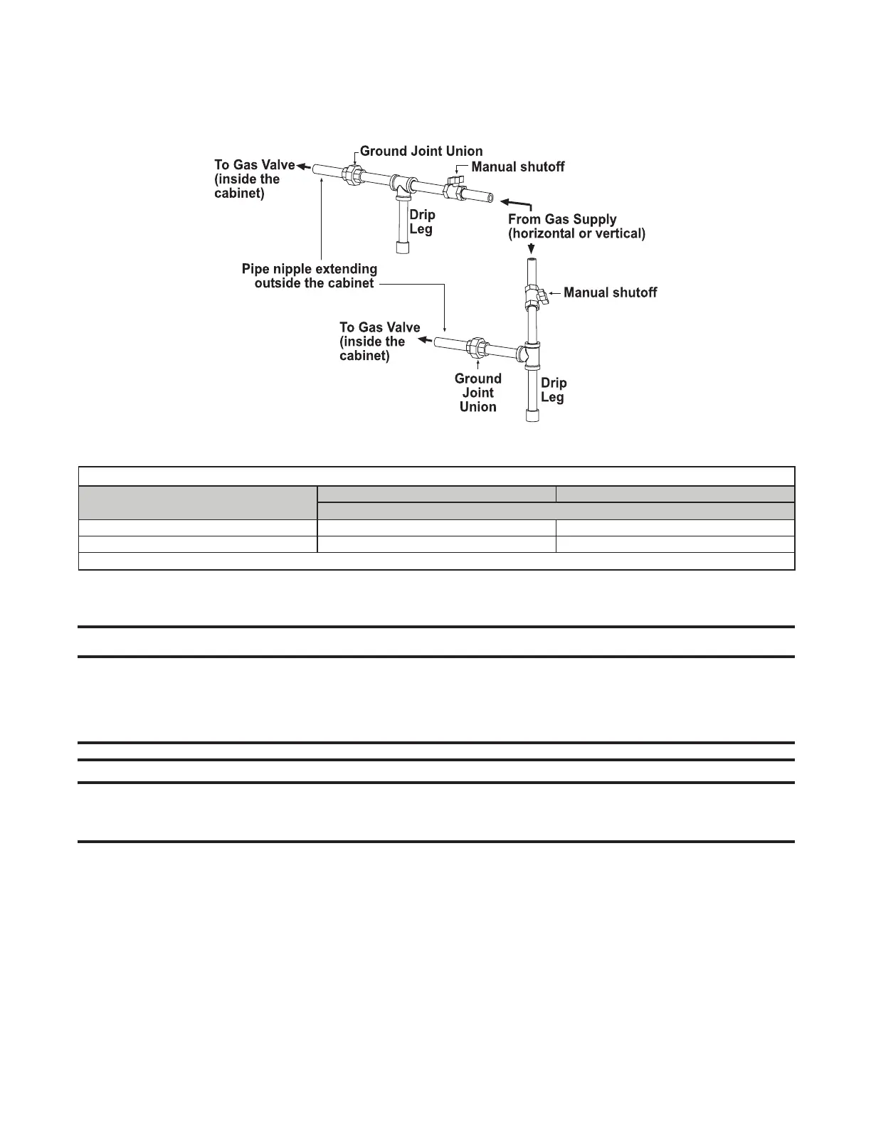
• Leak-test all connections by brushing on a leak-detecting solution. Bleed trapped air from gas lines as needed.
• The gas connection is made at the pipe nipple that extends outside the cabinet, as shown in Figure 8. Gas
connection sizes are listed in Table 11.
Figure 8. Gas Connections
Table 11. Gas Connection Sizes
Unit Size
Natural Gas Propane
Connection (Inches)*
030–200 1/2 1/2
225–400 3/4 3/4
*Connection size for a standard unit (not gas supply line size).
Electrical Connections
⚠ CAUTION ⚠
• Route wires so that they do not contact the flue wrapper or venter housing.
• If any of the original wire supplied with the appliance must be replaced, it must be replaced
with wiring material having a temperature rating of at least 105°C, except for limit control, flame
rollout, and sensor lead wires which must be rated at 150°C.
NOTES:
• Ensure that all wiring is in accordance with the wiring diagram provided with the unit.
• A two-stage valve circuit is NOT available on all models.
• All electrical wiring and connections, including electrical grounding MUST be made in accordance with the National
Electric Code ANSI/NFPA No. 70 (latest edition) or, in Canada, the Canadian Electric Code, Part 1 (CSA C.22.1).
In addition, the installer should be aware of any local ordinances or gas company requirements that might apply.
• Check the rating plate on the heater for the supply voltage and current requirements. A dedicated line voltage
supply with a disconnect switch should be run directly from the main electrical panel to the heater.
• All external wiring must be within approved conduit and have a minimum temperature rise rating of 60°C. Conduit
must be run so as not to interfere with the heater access panel.

 Loading...


