INSTALLATION—CONTINUED
Electrical Connections—Continued
• If the installation requires a stepdown transformer (option CG on some models), follow the instructions shipped
with the option package for installing the transformer.
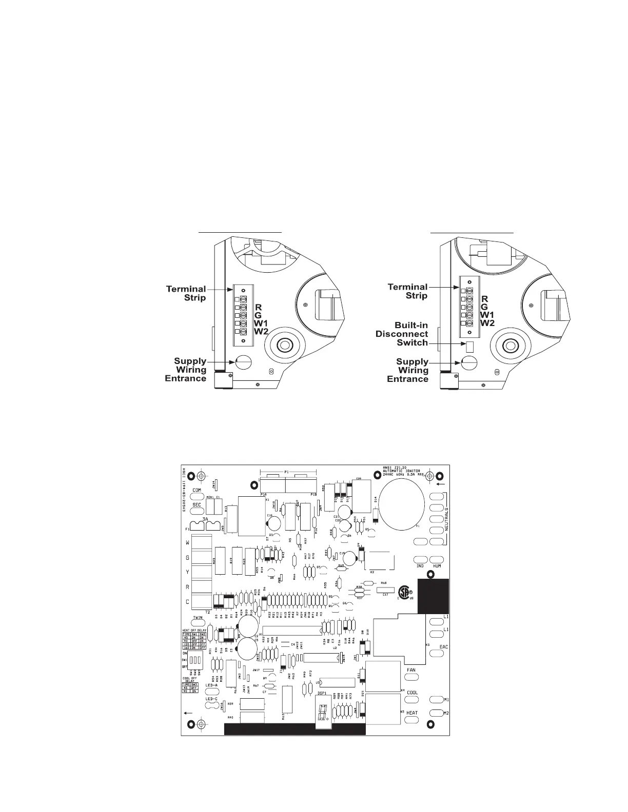
• UDZ and UBZ units have a built-in disconnect switch (20A@115V or 10A@230V rating).
• The supply wiring enters at the rear of the heater, as shown in Figure 9. For UBX and UDX models, the supply
wiring connects directly to leads on the integrated circuit board. For UBZ and UDZ models, the supply wiring
connects to the disconnect toggle switch.
• The terminal strip for 24V control connections is located on the outside of the cabinet at the back of the heater, as
shown in Figure 9. Wires from the terminal strip are factory-wired to the circuit board.
18
UBX-UBZ-UDX-UDZ-IOM (07-23) 1034344-K
Figure 9. Supply Wiring Entrance and Control Connection Terminal Strip
• The circuit board (see Figure 10) is located inside on the bottom of the control compartment. The circuit board is
polarity sensitive. It is advisable to check the electrical supply to ensure that the black wire is the hot wire and that
the white wire is the neutral wire. The hot wire must be connected to terminal L1 on the circuit board.
C
C
Rear View Separated
Combustion Model
Rear View Standard
Power Vent Model
NOTE: The size of
heater illustrated
has a vertical
terminal strip.
Some sizes have
a horizontal
terminal strip.
Figure 10. Circuit Board (DSI Control Module)

 Loading...


