37
UBX-UBZ-UDX-UDZ-IOM (07-23) 1034344-K
1. If heater has been installed, turn OFF gas and disconnect electric power.
2. Remove access panel and disconnect fan motor wires, capacitor wires at capacitor, and ground screw.
3. Remove assembled parts (fan guard, motor, and fan blade).
4. Disassemble and replace part(s) as needed.
5. Reassemble using replacement part(s) as needed and original parts.
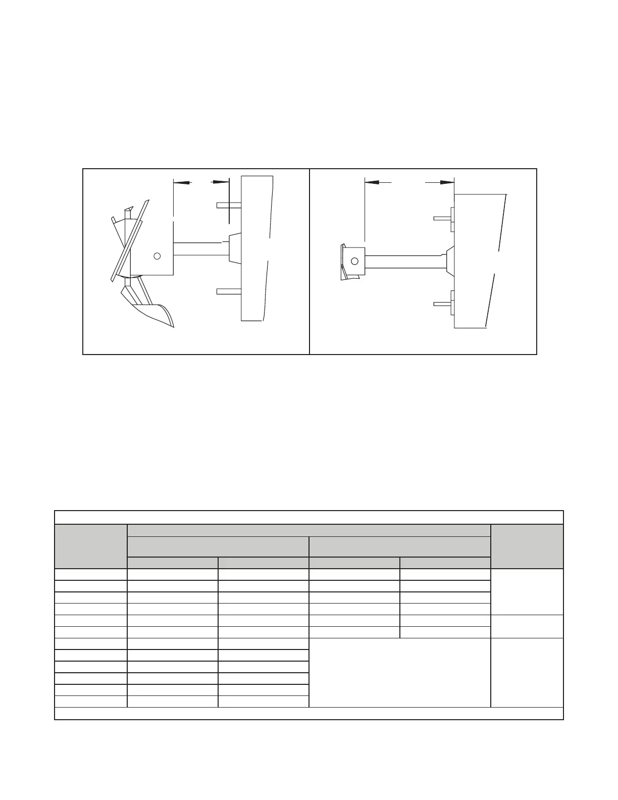
6. Ensure that fan blade is in proper position on shaft (see Figure 17) and that blades are properly spaced (refer
to Table 18).
Figure 17. Fan Blade Positioning and Spacing
7. Position assembly on heater and attach fan guard.
8. Rotate fan blade to check for adequate clearance. If adjustment is required, loosen mounting screws, reposition
fan guard, and tighten screws. Repeat until assembly is positioned properly.
9. Reconnect fan motor wires in accordance with wiring diagram.
10. Install access panel.
11. Restore electric power to heater and turn ON gas.
12. Follow instructions on lighting instruction plate to light heater.
13. Check for proper heater operation.
Table 18. Fan Blade Spacing
Unit Size
Dimension A*
Setscrew Torque
(Inch-Pounds
(±10))
Standard Wire Fan Guard
with 0.5 Inch (13 mm) Spacing
Option AZ8 Wire Fan Guard
with 0.334 Inch (8.5 mm) Spacing
Inches Millimeters Inches Millimeters
030 1 25 1 25
80
045 9/16 14 1-1/16 27
060 1-1/2 38 1-3/4 44
075 2-1/8 54 1-1/2 38
100 2-3/8 60 2-3/8 60
120
125 2-5/16 59 2-1/8 54
150 2-3/8 60
— 130
175 2-1/8 54
200 1-5/8 41
225, 250, 300 2 51
350 1-7/8 48
400 1-3/8 35
*See Figure 17.
A
A
Motor
Fan Blade
UNIT SIZES 030–250
UNIT SIZES 300–400
Fan Blade
Motor

 Loading...


