12
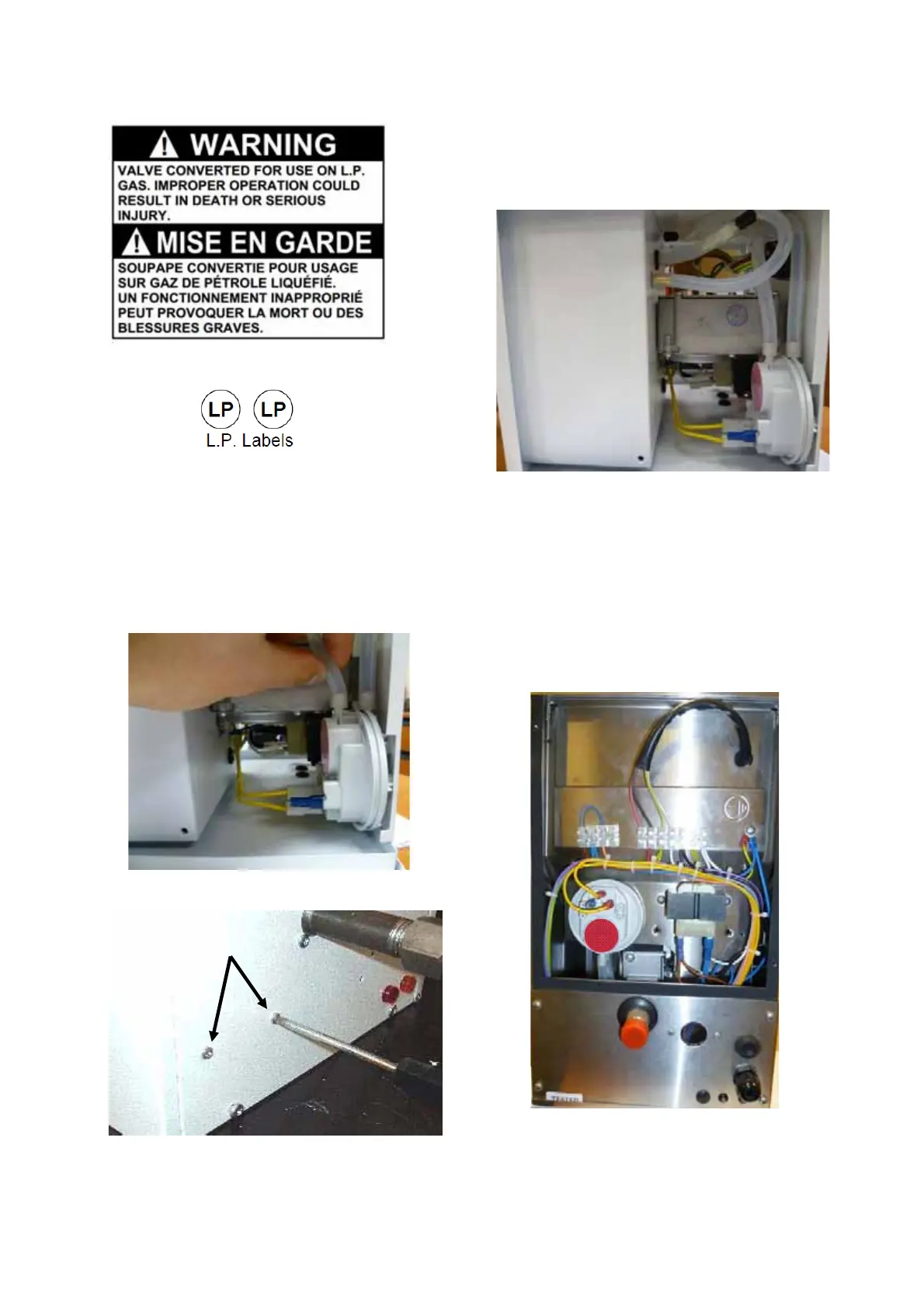
Step 4: Fit the new air pressure switch (with red
label), ensuring the cables and terminal cap are
installed correctly and the silicon tubes are connected
as shown below.
Section 8a
Air Pressure Switch Replacement (200kBTU VPS).
Step 1: To gain access to the pressure switch loosen
screw in burner lid and open left hand access door.
The pressure switch has a brown label.
Step 2: Disconnect the silicone tubes, cables and
terminal cap from the pressure switch.
Step 3: Remove the two screws arrowed below.
Step 5: Close access door and tighten screw in
burner lid.
Section 8b
Air Pressure Switch Replacement (200kBTU VPT,
VCS/VCT).
Step 1: The pressure switch can be accessed by
removing the top panel at the rear of the burner. This
is secured by 4 screws.
Step 2: Disconnect the silicone tubes, cables and
terminal cap from the pressure switch.
 Loading...


