13
Step 3: Remove the two electrical chassis retaining
screws (arrowed).
Step 4: The air pressure switch can now be removed
by unscrewing from the back plate.
It may be necessary to partially disconnect the chassis
wiring to access the pressure switch mounting screws
at the rear.
Step 5: Fit the new air pressure switch (with a red
label) ensuring the cables and terminal cap are
installed correctly and the silicon tubes are connected
as shown below.
Step 6: Close access door and replace the fixing
screws.
Section 9a
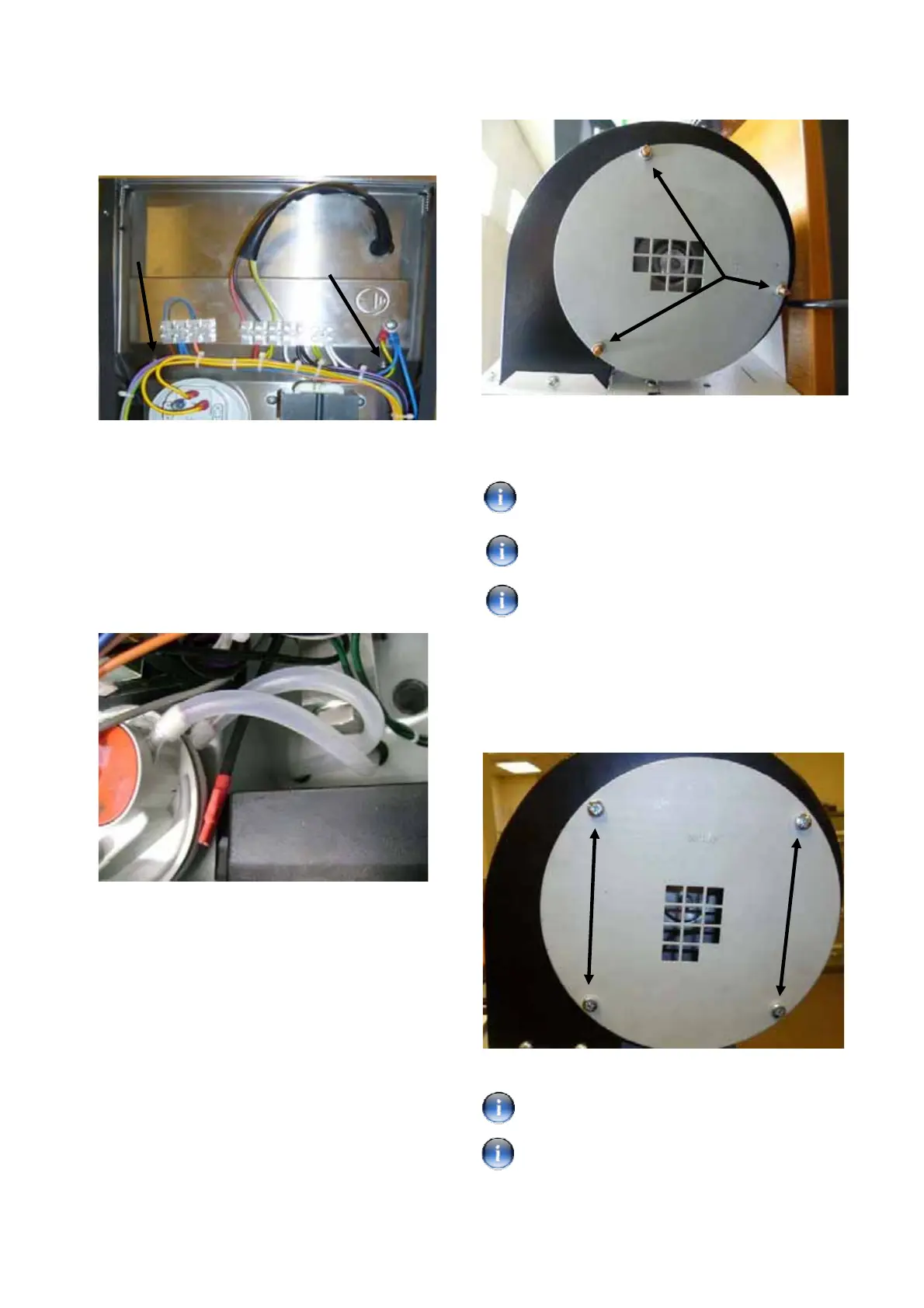
Fan Orifice Plate Replacement (3 screws VPS).
Step 1: Remove the 3 off 8mm nuts (arrowed) securing
the fan orifice plate with an 8mm wrench. Slide orifice
plate off the 3 protruding studs.
Section 9b
Fan Orifice Plate Replacement (4 screws VPS).
Step 1: Using a No.2 crosshead screwdriver remove
the four screws (arrowed) securing the fan orifice plate.
Remove plate.
Step 2: Fit the replacement fan orifice plate. Re-attach
the 3 x 8mm nuts (arrowed) turning clockwise, using
the wrench to secure to the combustion fan.
Take care not to cross thread the fasteners.
See Section 13 Table 1 for correct fan orifice
plate identification.
For high altitude conversion see Section 12 for
correct high altitude fan orifice plate identification.
Step 2: Fit the replacement fan orifice plate and
secure with the same four screws.
See Section 13 Table 2 for correct fan orifice
plate identification.
Take care not to cross thread the screws.
 Loading...


