14
Section 9c
Fan Orifice Plate Replacement (3 screws VPT, VCS/
VCT).
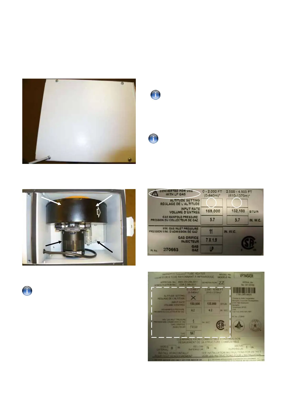
Step 1: Remove the top cover of the burner using a no.2
crosshead screwdriver to expose the combustion fan.
Step 2: Remove the four screws (arrowed), three of
which can not be seen in the photograph. Lift out the
fan assembly to access the fan.
Step 3: Follow the procedure in Section 8a to change
the fan orifice plate.
See Section 13 Table 3 for correct fan orifice
plate identification.
Step 4: Refit the fan and cover.
Section 9d
Fan Orifice Plate Replacement (4 screws VPT, VCS/
VCT).
Step 1: Remove fan following procedure in Section 8c.
Step 2: Follow procedure in Section 8b to change the
fan orifice plate.
See Section 13 Table 4 for correct fan orifice
plate identification.
Step 3: Refit the fan and cover.
Section 10
Data Badge Replacement (all models).
Ensure the single stage LP conversion label is
used on VPS/VCS burners and the two-stage LP
conversion label is used when converting VPT/VCT
burners.
Step 1: Locate the LP conversion data label.
Step 2: Indicate the altitude setting of the appliance by
placing an ‘X’ in the appropriate box highlighted below.
Step 3: Affix new label over the technical data section
of the natural gas data label as shown below.
 Loading...


