Form I-X, P/N 150491 R7, Page 7
5.0 Suspending or
Mounting the
Furnace
5.1 Weight
5.2 Suspending the
Furnace
Before installing the furnace, check the supporting structure to be used to verify that it
has sufcient load-carrying capacity to support the weight of the unit.
WARNING: Unit must be supported level for proper operation.
Do not place or add additional weight to the suspended unit.
These duct furnaces have two-point suspension. See hanger centerline dimensions in
FIGURE 5, page 6.
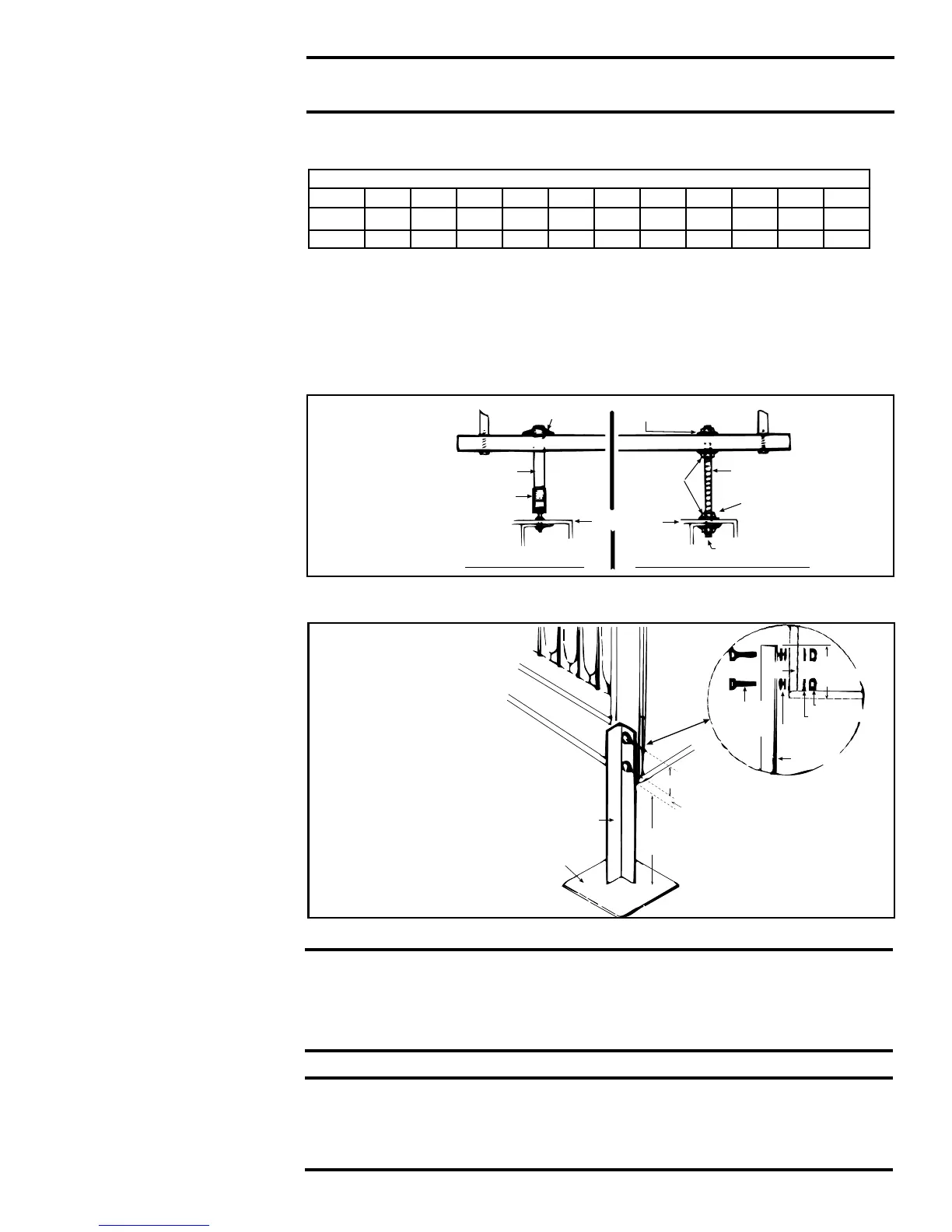
At each suspension point, the furnace is factory-equipped with a free-turning, female,
1" (NPT), pipe hanger. Suspend by connecting the pipe hanger to a 1" threaded pipe.
See FIGURE 6 (left side).
As an alternative method, the factory-installed pipe hanger may be removed and the
heater suspended as illustrated on the right in FIGURE 6.
Net Weight
Size 75 100 125 150 175 200 225 250 300 350 400
lbs 150 150 163 182 186 224 231 276 286 320 355
kg 68 68 74 83 84 102 105 125 130 145 161
FIGURE 6 -
Suspending
the Furnace
A minimum of 3" (76mm) clearance is required from the bottom of the unit to a combus-
tible surface. See FIGURE 7 for an illustration of eld-fabricated supports.
5.3 Mounting the
Furnace
FIGURE 7 -
Field-
Fabricated
Support
NOTE: Drawing is
not proportional;
comply with dimen-
sions as written.
6.0 Mechanical
6.1 Gas Piping and
Pressures
6.1.1 Gas Supply and Connections
WARNING: This appliance is equipped for a maximum gas supply
pressure of 1/2 psi, 3.4 kPa, or 14 inches water column. Supply
pressure higher than 1/2 psi requires installation of an additional
service regulator external to the unit.
PRESSURE TESTING SUPPLY PIPING
Test Pressures Above 1/2 PSI: Disconnect the heater and manual valve
from the gas supply line which is to be tested. Cap or plug the supply line.
Test Pressures Below 1/2 PSI: Before testing, close the manual valve on
the heater.