Form I-X, P/N 150491 R7, Page 20
8.4.4 Optional Electronic Modulation
The type and capability of the electronic modulation system depends on the option
selected. Electronic modulation options are identied by a sufx to the Serial No.
printed on the heater rating plate. AG7 is identied as MV-1; AG8 is identied as MV-3;
AG9 is identied as MV-4; and AG21 is identied as MV-A.
Electronic Modulation between 50% and 100% Firing Rate (Options AG7, AG8,
AG9) - Depending on the heat requirements as established by the thermistor sensor,
the burner modulates between 100% and 50% ring. The thermistor is a resistor that
is temperature sensitive in that as the surrounding temperature changes, the Ohms
resistance changes through the thermistor. This change is monitored by the solid state
control center (amplier) which furnishes varying DC current to the modulating valve
to adjust the gas input.
Each modulating valve is basically a regulator with electrical means of raising and
lowering the discharge pressure. When no DC current is fed to this device, it functions
as a gas pressure regulator, supplying 3.5" w.c. pressure to the main operating valve.
Refer to the wiring diagram supplied with the furnace for proper wiring connections.
Electronic modulation for heating controlled by a specially designed room thermo-
stat (60°-85°F) is identied as Option AG7. Electronic modulation control systems for
makeup air applications controlled by a duct sensor and temperature selector (55-
90°F) are identied as either Option AG8 or Option AG9. The temperature selector set-
ting for Option AG8 is on the amplier; Option AG9 has a remote temperature selector.
Both systems are available with an override thermostat.
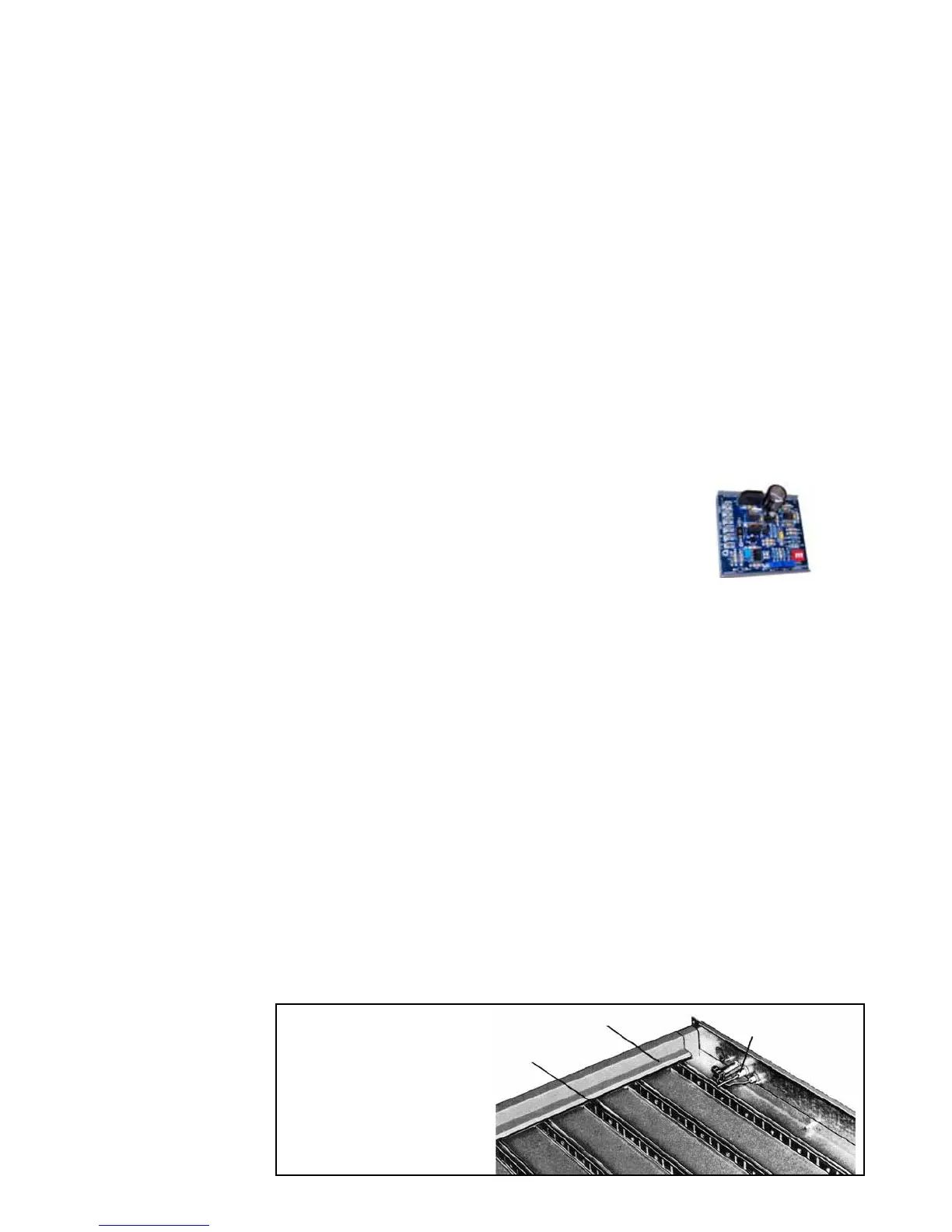
Computer Controlled Electronic Modulation between
50% and 100% Firing Rate (Option AG21) - With this
option the furnace is equipped with a Maxitrol signal condi-
tioner which operates much the same way as the amplier
above to control the regulator valve. The conditioner accepts
an input signal of either 4-20 milliamps or 0-10 volts from a
customer-supplied control device such as a computer. With
the dip switches on the conditioner in the "on" positions, the
conditioner accepts a 4-20 milliamp signal. In the "off" posi-
tions, the conditioner accepts a 0-10V signal. The conditioner converts the signal to
the 0 to 20 volt DC current required to control the modulating valve.
Signal Conditioner
in Option AG21
8.5 Pilot and
Ignition
Systems
Model X furnaces have an intermittent spark pilot system. The horizontal pilot is located
in the control end of the burner rack and is accessible after the control compartment
panel has been removed. All pilots are target type with lint-free feature. Pilot gas pres-
sure should be the same as supply line pressure. (See Paragraph 6.1.) If required,
adjust the pilot ame length to approximately 1-1/4" with pilot adjustment screw in
control valve body.
Service NOTE: If your Model X heater was manufactured prior to 10/2003, it may have
a standing pilot. See wiring diagrams in the APPENDIX, page 30..
Spark Ignition Safety Pilot System - Natural gas units are equipped with a spark
ignited intermittent safety pilot system that shuts off the pilot gas ow between heat
cycles. Propane units (or as an option on natural gas units) require a lockout device.
The lockout device stops the gas ow to the pilot if the pilot fails to light in 120 seconds.
The lockout feature has a one hour retry and requires manual set by interruption of the
thermostat circuit. Refer to the wiring diagram supplied with the unit for pilot system
identication and proper wiring. Pilot with lockout is Option AH3; spark pilot without
lockout is Option AH2.
Spark Pilot
Flash Carryover
FIGURE 21 -
Burner Rack
with Spark
Pilot
Main Burner
8.0 Controls
(cont'd)
8.4 Gas Controls
(cont'd)