Form I-X, P/N 150491 R7, Page 5
3.2 Preparing the
Furnace for
Installation
Read this booklet and become familiar with the installation requirements of your par-
ticular furnace. If you do not have knowledge of local requirements, check with the
local gas company or any other local agencies who might have requirements concern-
ing this installation. Before beginning, make preparations for necessary supplies, tools,
and manpower.
Check to see if there are any eld-installed options that need to be assembled to the
furnace prior to installation.
Option Parts -- Some gas control options will have parts either shipped loose with the
heater or shipped separately. If your unit is equipped with any of the gas control options
listed below, be sure these parts are available at the job site.
Application Option Shipped Separate Components
Heating -- Gas Control AG7 Thermostat, P/N 48033
Makeup Air -- Gas
Control Options
AG3, AG8 Control Switch, P/N 29054
AG9
Remote Temperature Selector, P/N 48042
Control Switch, P/N 29054
AG15
Remote Temperature Selector, P/N 115848
Stage Adder Module, P/N 115849
Control Switch, P/N 29054
Other shipped-separate options could include a vent damper, a power venter, a gas
shutoff valve, a condensate drain tting, a thermostat, and/or a disconnect switch.
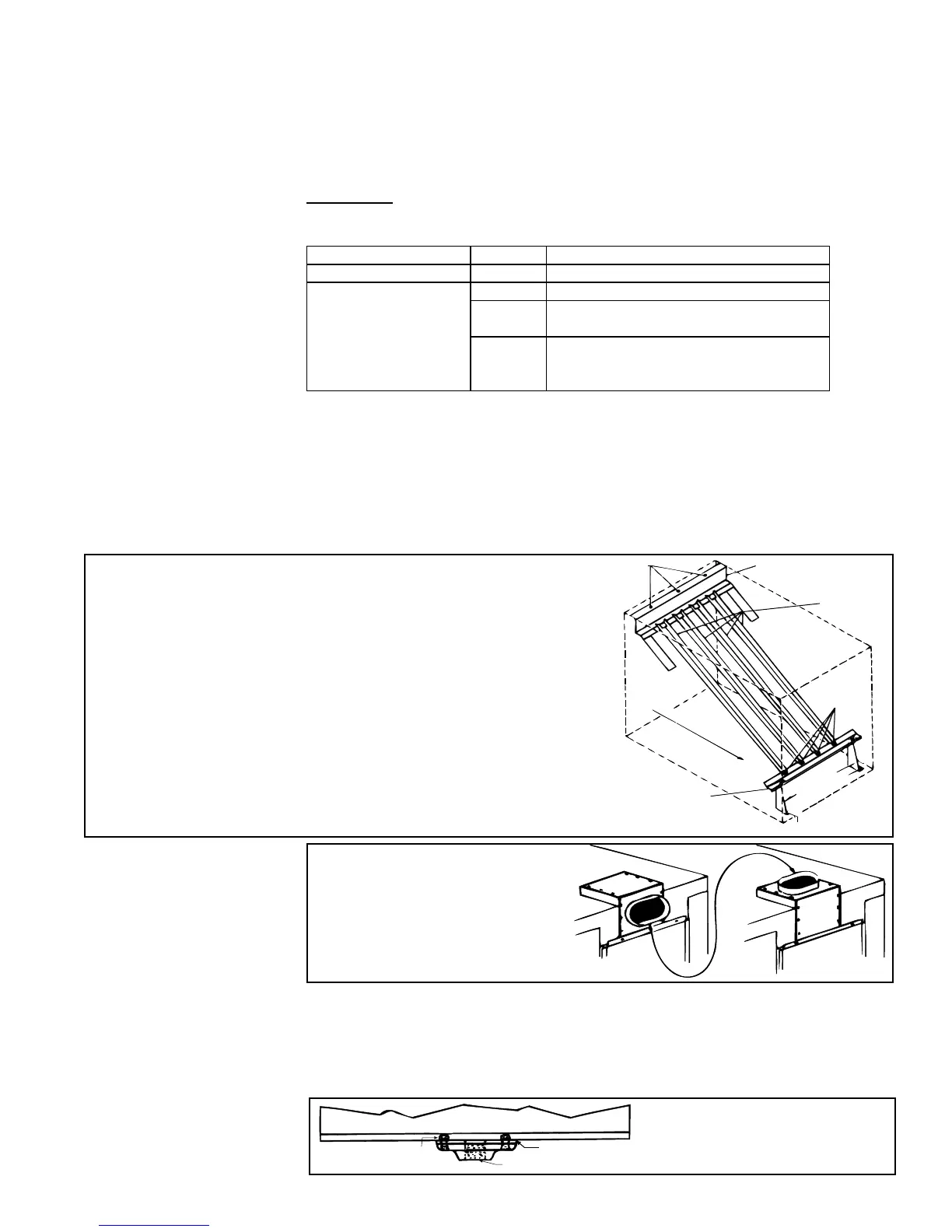
FIGURE 2 - Heat Exchanger Directional Air Bafes
Top Baffle
Support
Screws
B
Bottom
Baffle Support
Brackets
Air Discharge
Direction of Airflow
Screw C
Right
Left
Screws A
Screw C
Airflow
Baffles
3.2.1 Instructions for
Reversing Airow by
Changing Directional
Air Bafes in the Heat
Exchanger
Model X furnaces are equipped with directional air bafes between the heat exchanger
tubes. Facing the control compartment of the furnace, the standard direction of airow
is from left to right. An installation requiring direction of airow from right to left when
facing the control compartment requires repositioning of the directional air bafes at
the installation site. Follow the instructions in FIGURE 2 to change the position of
bafes:
a) Remove Screws "A". Individually lift each bafe slightly and slide
forward. Remove all bafes completely from the heat exchanger.
b) Remove Screws "B" and the top bafe support assembly.
Re-position the assembly to the opposite end of the heat
exchanger and attach.
c) Remove Screws "C" and the assembled bottom bafe support
and brackets. Plug the holes in the heat exchanger bottom by
re-inserting the screws in the holes. Position the assembly on
the opposite end of the heat exchanger and attach using eld-
supplied sheetmetal screws.
d) Re-install all of the individual bafes by reversing the procedure
in Step a) above.
3.2.2 Change the Vent
Outlet Direction
FIGURE 3 - Horizontal
or Vertical Flue
Connection
To change orientation (vertical
or horizontal) of the ue
connection: (1) Remove screws;
(2) Reverse position; (3) Re-fasten.
The vent outlet may be horizontal
or vertical.
FIGURE 4 - Condensate
Drain, Option CS1
(P/N 31765)
Seal holes in bottom pan. Terminate
drain outside of building. Periodic
cleaning of the condensate collector
and disposal system is required.
3.2.3 Install
Condensate Drain,
Option CS1
Condensate can form in the heat exchanger of furnaces installed as makeup air units
or when installed downstream from a cooling coil. Under these conditions, a drain
ange, Option CS1, may be installed on the furnace bottom as shown in FIGURE 4.
When using Option CS1, seal all corners and the four square holes in the bottom pan
edge. NOTE: A 4-inch (102mm) minimum clearance is required under the furnace if a
90° street elbow is used.