Form I-X, P/N 150491 R7, Page 24
10.0 Maintenance
and Service
WARNING: If you turn off the power supply, turn off the gas.
See Hazard Levels, Page 2.
This unit will operate with a minimum of maintenance. To ensure long life and satis-
factory performance, a furnace that is operating under normal conditions should be
inspected every four months. If the furnace is operating in an area where an unusual
amount of dust or soot or other impurities are present in the air, more frequent inspec-
tion is recommended.
10.1 Maintenance
Schedule
The following procedures should be carried out at least annually (See Para-
graphs 10.2.1- 10.2.4 for specic instructions.):
Clean all dirt and grease from the primary and secondary combustion air openings.
Check the gas valve to ensure that gas ow is being shutoff completely.
Clean the heat exchanger both internally and externally.
Check the pilot burner and main burners for scale, dust, or lint accumulation.
Clean as needed.
Check the vent system for soundness. Replace any parts that do not appear
sound.
Check the wiring for any damaged wire. Replace damaged wiring. (See the wiring
diagram for replacement wiring requirements.)
CAUTION: When cleaning, wearing eye protection is recommended.
NOTE: Use only factory-authorized replacement parts.
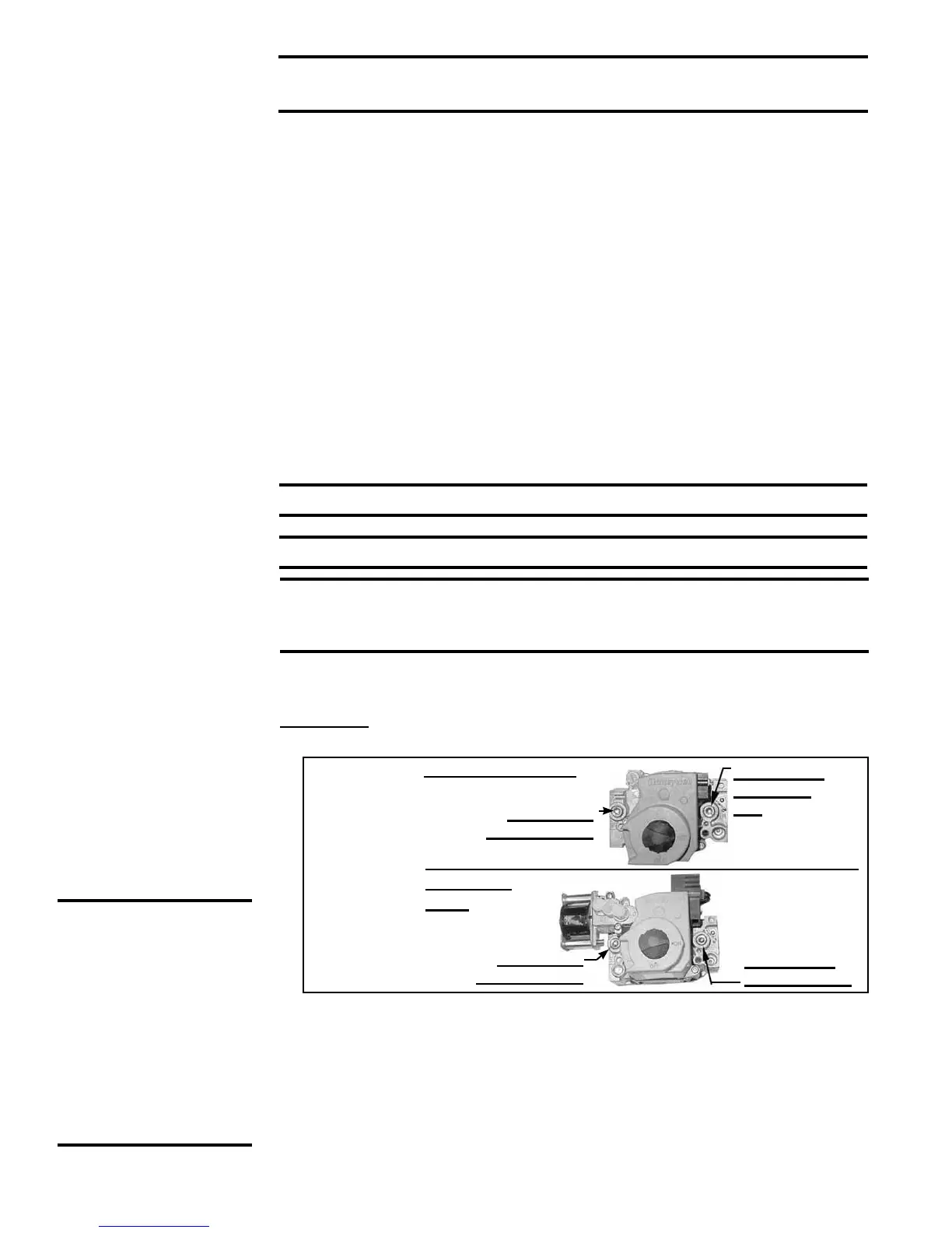
10.2.1 Operating Gas
Valve
Single-Stage Valve
Two-Stage
Valve
1/8" INLET
Pressure Tap
1/8” Outlet
Pressure
Tap
1/8" INLET
Pressure Tap
1/8” Outlet
Pressure Tap
FIGURE
24 - Gas
Valve
Shutoff
Check
2) With the manual valve turned off to prevent ow to the gas valve, connect a
manometer to the 1/8” inlet pressure tap in the valve. NOTE: A manometer (uid-
lled gauge) with an inches water column scale is recommended.
3) With the eld-installed manual valve remaining closed, observe the manometer for
two to three minutes for an indication of gas pressure. No pressure should be indi-
cated on the manometer.
If the manometer indicates a gas pressure, the eld-installed manual gas valve
must be replaced or repaired before the combination gas valve can be checked.
WARNING: The operating valve is the prime safety shutoff. All
gas supply lines must be free of dirt or scale before connecting
to the unit to ensure positive closure. See Hazard Levels, page 2.
Remove external dirt accumulation and check wiring connections.
The combination gas valve must be checked annually to ensure that the valve is shut-
ting off gas ow completely.
Instructions:
1) Locate the 1/8” FPT INLET pressure tap on the combination valve (FIGURE 24).
CAUTION: DO NOT
bottom out the gas
valve regulator
adjusting screw.
This can result
in unregulated
manifold pressure
causing excess
overre and heat
exchanger failure.
NOTE: Operational
pressure settings and
instructions for checking
pressure settings are in
Paragraph 6.1.
10.2 Maintenance
Procedures