Form I-X, P/N 150491 R7, Page 19
8.4.2 Optional Two-
Stage Operation for
Heating Only
The standard combination control valve is replaced with a two-stage combination gas
control valve providing for low re or high re operation controlled by a two-stage
thermostat. First stage (low re) is factory set (not eld adjustable). Both high and low
stages are controlled by a Servo regulator, maintaining constant gas input under wide
variations in gas supply pressure. See instructions packed with the unit for specic gas
valve specications, wiring, and operating instructions.
8.4.3 Optional Two-
Stage Operation for
Makeup Air
Two-stage makeup air units are equipped with a two-stage gas valve, but instead of
control from a two-stage room thermostat, the outlet air temperature is monitored and
controlled by a two-stage ductstat. When the discharge air temperature drops to the
setpoint, low re is energized. If low re cannot satisfy the ductstat setting, high re is
energized.
Makeup air applications are usually adjusted to discharge an outlet air temperature
between 65°F and 75°F. In all applications, the allowable temperature rise of the fur-
nace in the installation dictates the limits of the ductstat temperature setting.
Depending on the option selection, the factory-installed sensor is either eld-connected
by capillary tubing to the unit-mounted ductstat (FIGURE 18) or electrically connected
to a remote electronic temperature selector (FIGURE 20). The remote temperature
selector is available with or without a display module.
See FIGURE 19 for a general location of the factory-installed sensor with either the
factory-mounted or the remote ductstat selector option.
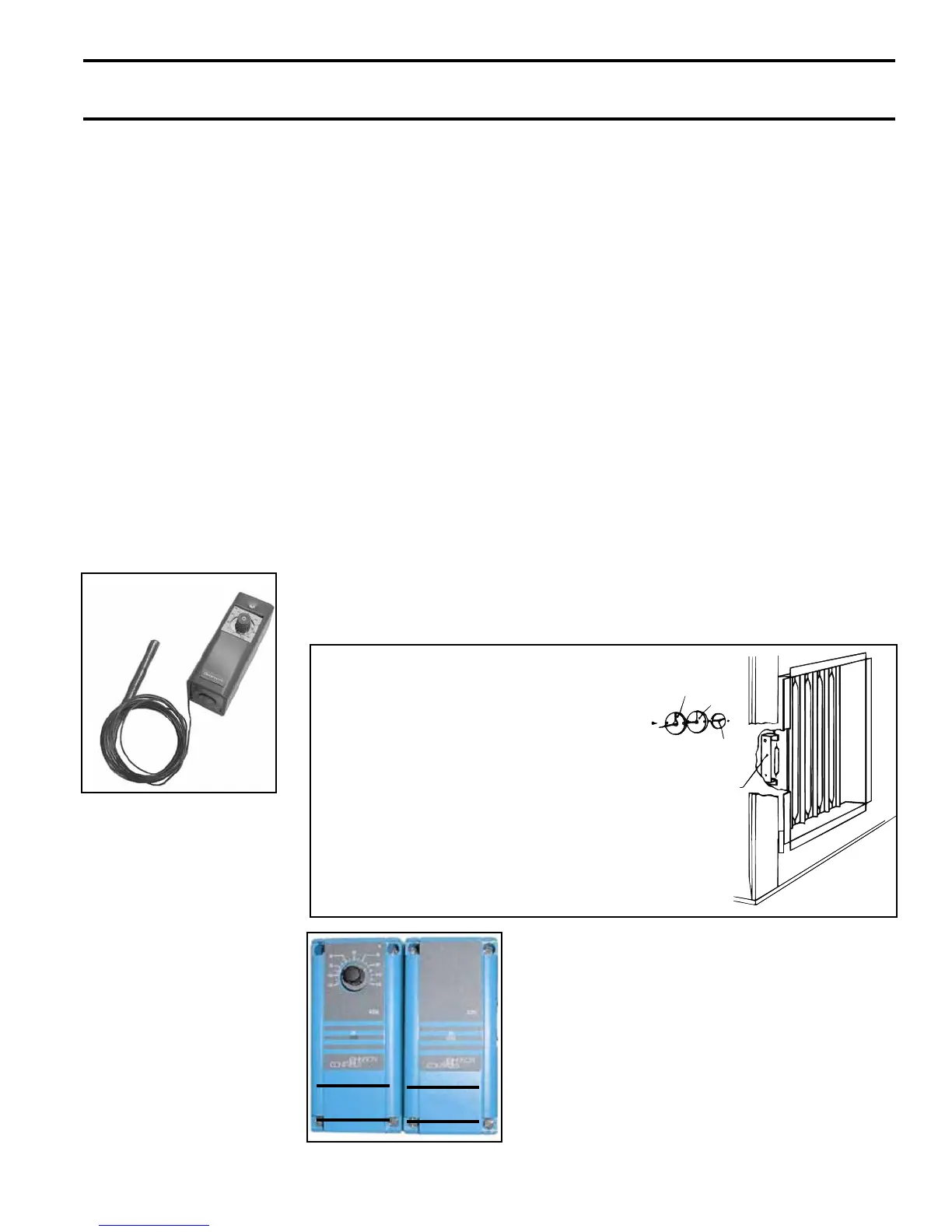
Optional Ductstat with Capillary Tubing (Option AG3) - The ductstat illustrated in
FIGURE 18 is used with Option AG3. The control is set to 70°F and has an adjustable
range with a xed differential of 2-1/2°F. Due to different CFM settings and outside air
temperature, the average downstream outlet temperature may not match the ductstat
setting exactly. After the installation is complete, adjust the setpoint of the ductstat to
achieve the desired average outlet air temperature.
Adjustable range
0-100°F with a xed
differential of 3°F.
FIGURE 18- Ductstat
Control in Option AG3
FIGURE 19 - Duct Temperature
Sensor Location
Sheetmetal
Retaining Plate
Gasket
Sensor Capillary
Sensor Bracket
(NOTE:
.)
1. Remove access panel in
ductwork adjacent to control com-
partment access panel.
2. Element is retained by spring
clips.
3. Round gasket and metal retaining
plate provide air tight seal for
capillary and must be removed to
remove the element.
WARNING: The operating valve is the prime safety shutoff. All gas supply lines must
be free of dirt or scale before connecting the unit to ensure positive closure.
FIGURE 20 - Ductstat
Control in Two-Stage
Makeup Air Control
Option AG15 - (A)
Remote Temperature
Selector; (B) Stage-
Adder Module
(A)
(B)
Optional Ductstat with Electronic Remote Set-
point Module (Option AG15) - The sensing probe
is eld-wired to a remote temperature selector. The
temperature selector has an operating range to
120°F. The remote modules are shipped separately
for eld installation. Follow the wiring diagram with
the unit and the manufacturer's instructions for wiring
and installation.
There will be one module for selecting temperature
and one-stage adder module as illustrated in FIG-
URE 20.