3. Loosen the front and side lock screws at the top and/or bottom of the track support column to telescope the support to
the ground, depending on how much support length you need. Retighten the lock screws.
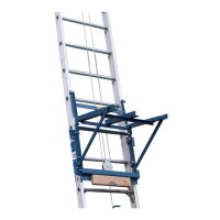
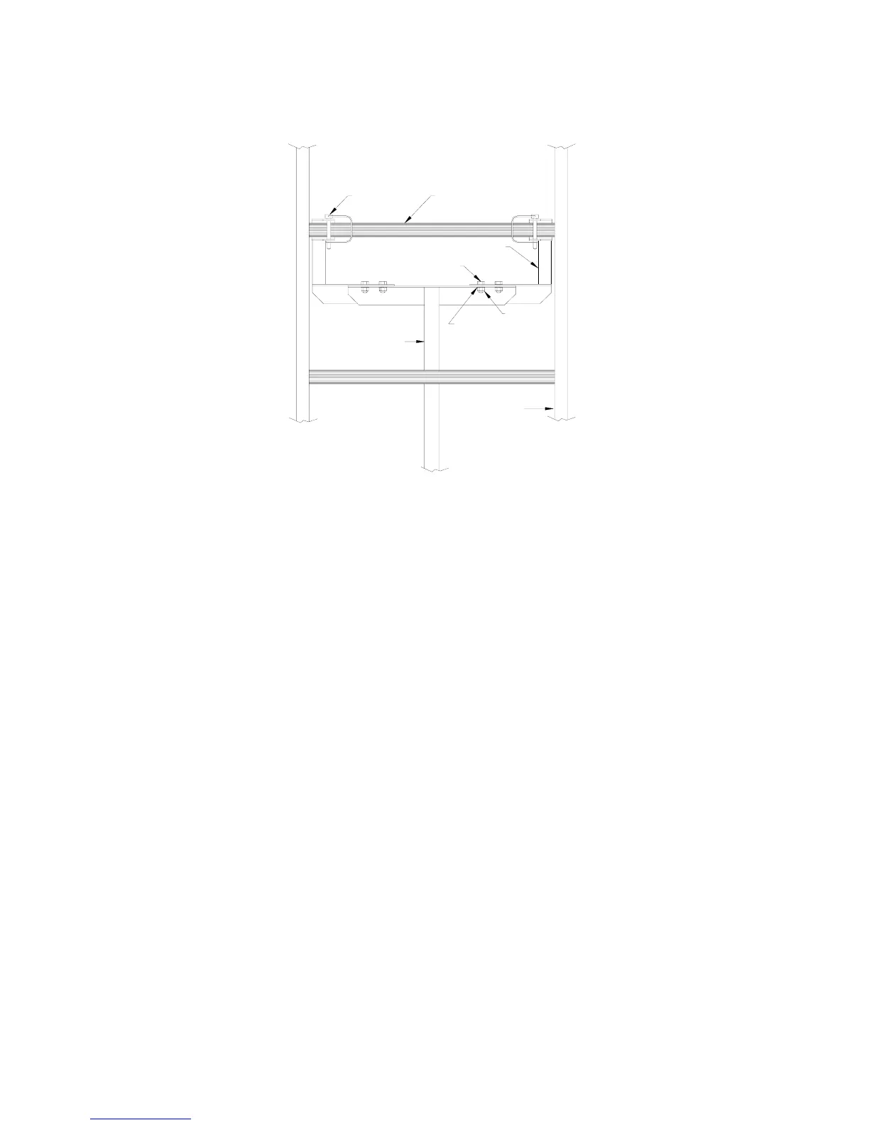
Figure 3-4.
Track Support Assembly
Track Support
Hex Head Cap Screw
Lock Pin
Knuckle
Cross Tie
Ext. Tooth Washer
Nut
Track Rail
3.8 OPTIONAL EQUIPMENT FOR THE PRO400
The following options can customize your hoist for your particular operation.
1. PRO400 Plywood Carrier Attachment
2. PRO400 Gravel Hopper
3. PRO400 Roller Angle Guide
3.8.1 Plywood Carrier Attachment
1. Remove the #18 platform stops.
2. Remove the two #16 platform braces to allow the platform to drop down into a vertical position.
3. Refer to Figure 3-5. Attach the two plywood carrier brackets using the existing platform stop holes and platform stop
hardware.
4. For extra load thickness capability, remove the wheels from the platform. Loads can be secured with bolts using
holes provided in the carrier.
5. Sheets of plywood can be placed on the carrier with either the 4 foot or 8 foot dimension “up”. If the 8 foot
dimension is up (vertical), the weight of the sheets will automatically tilt the stack when the carrier reaches the top of
the track. If the 4 foot dimension is up, more care must be taken to balance the stack left to right. The person
unloading must tilt the stack into the horizontal plane to slide it out of the carrier.
6. Material should be held against the track with a rope fastened to the carrier as shown in Figure 3-9. The person at the
top of the track holds the loose end. Keep the rope taut as the load is raised. Raise material slowly when nearing the
top of the track.
9