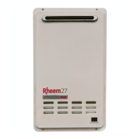
TM049 27L Continuous Flow Service Instructions
REV AL – Issued April 2019
This document is stored and maintained electronically by Rheem Technical Support. All printed copies are deemed “uncontrolled”.
Fault Finding Tests 8, 9 & 11
Conduct test during ignition attempt.
Using a multimeter set on the AC volts scale, measure the voltage between the two red wires at
base of the ignition module.
Normal voltage should be between 90 – 110VAC.
Conduct test with water flowing.
Using a multimeter set on the DC volts scale,
measure the voltage with multi-pin connector
plugged into terminal W, on control PCB.
Using a multimeter set on the kilo-ohms scale,
measure the resistance with multi-pin
connector unplugged from terminal W, on
control PCB.
4321
Y
Z
5 4 3 12
LED1
LED
DISPLAY
PLM-110
A.C 100V
3A80505
JAPAN
N
JAPAN
JAPAN
2 3 4
765
W
6
4
5 2
1
3
X
JAPAN
JAPAN
6
4
5 2
1
3
X
JAPAN
5 6 7
432
JAPAN
JAPAN
W
 Loading...