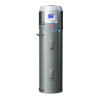
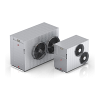
Commercial Air to Water Heat Pump Water Heater
36
CONNECTIONS - ELECTRICAL
AUXILIARY BOOST ELEMENT
If a single auxiliary boost element is supplied by Rheem,
remove bridging wire at the terminals marked ‘A7 and A9’
behind the element controller cover and connect the ter-
minal A7 and A9 to the voltage free terminal marked ‘VF’
in the heat pump enclosure to control the operation of the
boost element.
Where multiple auxiliary boost elements are required,
and the number of auxiliary boost elements matches the
number of heat pumps, each element may be interlocked
with an individual heat pump directly using the method
described above. In this case, the heat pumps should op-
erate independently and each have their own tank and
building flow temperature sensor connected.
Where the number of auxiliary boost does not match the
number of heat pumps or the heat pumps are connected
in a Primary/Secondary arrangement using LAN cables
(refer to next page), then the heat pumps must be con-
nected via LAN cables and control of the auxiliary boost
elements will be via the Primary heat pump using an in-
termediary relay arrangement. Refer to Application Guide
for more detail.
AUXILIARY BOOST HEATER (EX-
TERNAL TO STORAGE TANK)
Depending on the installation, an auxiliary heater and/or
boost pump may be supplied. Refer to Application Guide
for auxiliary boost options.
In the heat pump enclosure, terminals marked “SA”, “N”
and “GND” provide 24V to control the auxiliary heater
and/or auxiliary pump or multiple boost elements depend-
ing on the system design. Maximum current is 1A. Refer
to Application Guide for further information to connect
auxiliary boost heater.
NOTE: Where multiple heat pumps are required, the
heat pumps must be connected in a Primary/Second-
ary arrangement using LAN cables (refer to page 53),
and control of the auxiliary boost heaters will be via the
Primary heat pump. Refer to Application Guide for more
details.
480V/60HZ
Electric Heating Unit - Wiring Diagram.
Picture of heat pump terminal strip.
 Loading...