INSTALLAZIONE
I lavori di installazione, avviamento
e manutenzione del ventilconvet-
tore devono sempre seguire tutte
le norme, i regolamenti, i codici e
le normative su sicurezza e salute
e la più recente tecnologia.
Predisposizioni
Per il funzionamento dell’apparec-
chiatura bisogna predisporre un
collegamento idraulico con la cal-
daia/refrigaratore e un collegamen-
to elettrico 230V monofase.
Il controsotto deve essere in posi-
zione e deve essere stata praticata
un’apertura per alloggiare il ventil-
convettore.
Le dimensioni minime e massime
per l’apertura sono:
Le tubazioni devono essere già in-
stallate e le valvole devono essere
pronte per l’installazione.
I cavi da collegare all’apparecchio
devono essere già installati al sopra
del controsotto.
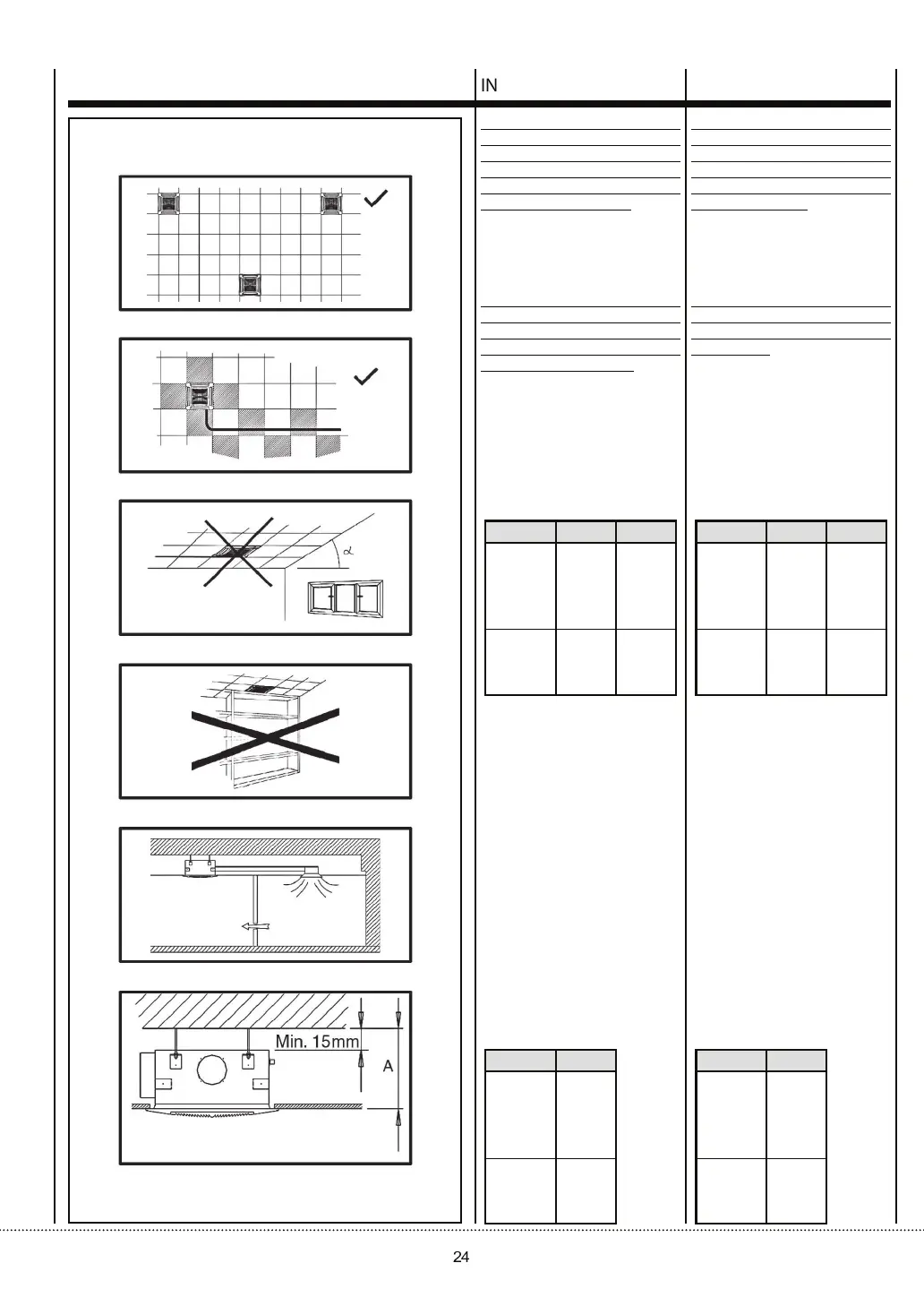
Luogo di installazione
I ventilconvettori Cassette vanno
installati esclusivamente ad incas-
so in controsotti.
Prevedere delle griglie sulle porte
per il ricircolo dell’aria.
Lo spazio minimo tra il controsof-
tto ed il sotto strutturale è di:
INSTALLATION
All operations of installation, start-
up and maintenance of the fan
coil unit must always been done
according to all health and safety
rules/regulations and to the most
updated technology.
Predispositions
To operate the appliance, connect
hydraulically to a boiler/chiller and
electrically to a 230 V single phase
power supply.
Prior to installation the following
conditions must be satised:
The suspended ceiling must be in
place and must have been cut out
for the fan-coil unit. The minimum
and maximum dimensions of the
cutout are as follows:
The pipework must have been
installed and the valving must be
ready for installation.
Cabling to the appliance must have
been installed above the suspended
ceiling.
Place of installation
Cassette fan-coil units are exclusively
designed for incorporation in suspended
ceilings.
Install grills on the doors for the air
circulation.
The minimum space between the
false ceiling and the ceiling is:
Modello
DIVA 20÷50
DIVA 60÷110
590 x 590
840 x 840
630 x 630
900 x 900
Minima Massima
Modello
DIVA 20÷50
DIVA 60÷110
310
345
A
DIVA 20÷50
DIVA 60÷110
310
345
A
Model
DIVA 20÷50
DIVA 60÷110
590 x 590
840 x 840
630 x 630
900 x 900
Model
Minimum Maximum