46
Il regolatore dovrà es-
sere posto esclusiva-
mente all’interno del
quadro metallico di derivazione.
Qualora venga posto all’esterno,
tutto il sistema macchina verrà con-
siderato non conforme alle norma-
tive applicabili.
The controller must only
be positioned inside the
metal shunt panel.
If it is positioned outside, the entire
machinery will be considered
non compliant with the applicable
standards.
È fondamentale utilizzare Regola-
tori aventi le caratteristiche (riferite
all’uscita 0-10Vdc):
s )MPEDENZADI
s -ASSIMAVELOCITË6DC
s &AN/&&CON66DC
It is very important that controllers
with the following specifications
are used (in reference to output
0-10Vdc):
s )MPEDANCE
s -AXIMUMSPEED6DC
s &AN/&&WITH66DC
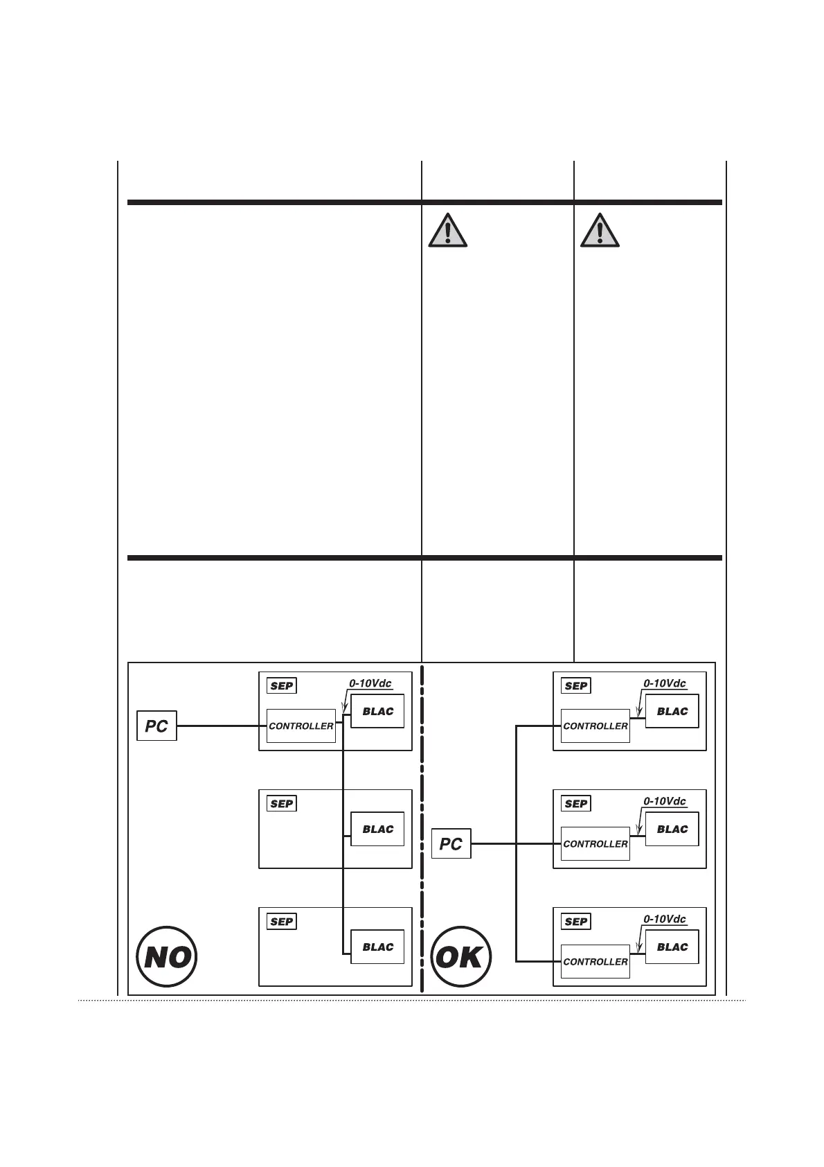
LIMITI D’IMPIEGO
APPLICAZIONE
Ciascuna unità INVERTER dovrà
recepire segnale 0-10Vdc con pro-
venienza interna al quadro di deri-
vazione. Pertanto non sarà pos-
sibile derivare da un regolatore il
medesimo segnale a comando di
più unità ventilconvettore.
LIMITS OF USE
Each INVERTER unit should receive
a 0-10Vdc signal from inside the
shunt panel. Therefore it is not
possible to shunt the same signal
from a controller to control multiple
fan coil units.
ISTRUZIONI
OPERATIVE PER
IL COLLEGAMENTO
DI PIÙ UNITÀ
CON UN UNICO
COMANDO
OPERATING
INSTRUCTIONS
FOR CONNECTING
MULTIPLE UNITS
WITH A SINGLE
CONTROLLER